
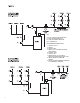
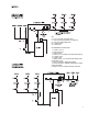
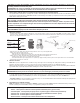
Install Instructions

7
9
. Troubleshooting the error codes:
S
ureStart Feature: The VT2218 is programmed with an automatic unblocking feature. In the case of a locked rotor condition, it will
attempt to unblock the rotor with a series of rapid oscillating actions. It will repeat this process up to 100 times. If still locked after
100 attempts, “LOCKED ROTOR” will apppear on the LCD. See error code listing below.
L
isted below are potential diagnostic error codes which will appear on the LCD display in case of a malfunction.
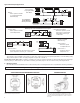
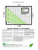
Testing the Sensors
A good quality test meter capable of measuring up to 5,000 kΩ (1 kΩ = 1000Ω) is required to measure the sensor resistance. In
addition to this, the actual temperature must be measured with a good quality digital thermometer.
First measure the temperature using the thermometer and then measure the resistance of the sensor at the VT2218. The wires from
the sensor must not be connected to the circulator while this test is performed. The wiring terminals are easily removed by pulling
them from the circulator. Using the chart below, estimate the temperature measured by the sensor. The sensor and thermometer
readings should be close. If the test meter reads a very high resistance, there may be a broken wire, a poor wiring connection or a
defective sensor. If the resistance is very low, the wiring may be shorted, there may be moisture in the sensor or the sensor may be
defective. To test for a defective sensor, measure the resistance directly at the sensor location.
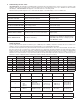
ERROR CODE* DESCRIPTION CORRECTIVE ACTION
SENSOR 1 MISSING Supply sensor disconnected. Reconnect sensor.
SENSOR 2 MISSING Return sensor disconnected. Reconnect sensor.
S
ENSOR 1 SHORTED
B
ad sensor.
R
eplace sensor.
SENSOR 2 SHORTED Bad sensor. Replace sensor.
AC INPUT UNDER VOLTAGE Low voltage problem. Check power supply.
AC INPUT OVER VOLTAGE High voltage problem. Check power supply.
LOCKED ROTOR Probable locked rotor or motor failure. Replace pump.
MOTOR OVER CURRENT Possible locked rotor or motor over current. Replace pump.
OVER TEMPERATURE PC Board overheating.
Pump will reduce current and speed until PCB
temperature is acceptable. If speed falls below
1650 RPM, pump will stop on safety. Cycle AC
power OFF/ON to restart.
SPEED TACO GRUNDFOS WILO B & G/XYLEM ARMSTRONG
1 003 Alpha-15-55 (1) - - -
2 006 Alpha-15-55 (2) - - Compass (1)
3
007
008
0015-1
0015-2
UP-15-42
UPS-15-58 (1)
UPS-15-58 (2)
Star S-2 (1)
Star S-21 (2)
NRF-25 (1)
NRF-25 (2)
Astro 230 (1)
Astro 230 (2)
Compass (2)
4 0015-3
UPS-15-58 (3)
Alpha-15-55 (3)
Star S-21 (3)
NRF-25 (3)
Eco-Vario
Astro 230 (3)
Compass (3)
Pump Cross Reference (Constant Speed Mode):
Temperature
Resistance Temperature Resistance Temperature Resistance Temperature Resistance
°F °C
Ω
°F °C
Ω
°F °C
Ω
°F °C
Ω
-30 -34
234,196 30 -1 34,558 90 32 7,334 150 66 2,045
-20 -29 165,180 40 4 26,099 100 38 5,828 160 71 1,689
-10 -23 118,018 50 10 19,900 110 43 4,665 170 77 1,403
0 -18 85,362 60 16 15,311 120 49 3,760 180 82 1,172
10 -12 62,465 70 21 11,883 130 54 3,050 190 88 983
20 -7 46,218 80 27 9,299 140 60 2,490 200 93 829
MODE TACO GRUNDFOS WILO B & G/XYLEM ARMSTRONG
Delta-T 008-VDT Alpha 15-55 Stratos Eco 16FX Eco-Auto 19-14 Compass 2020
Pump Cross Reference (Delta-T Mode):
* Flashing Displayed on LCD