
Install Instructions

4
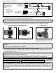
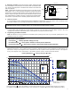
ACCEPTABLE MOTOR MOUNTING POSITIONS CASING ROTATION
To rotate the casing, remove the 4 motor screws and spin
the casing to the desired flow direction. Reattach the 4
screws (
5
⁄
32
"allens wrench required). Be sure body gasket
is seated evenly to prevent leakage. Tighten motor
screws to 34-42 in-lbs torque.
WARNING: Use supply wires suitable for 90°C. AVERTISSEMENT: Employer des fils d’alimentation adeqauts pour 90°C.
1. Location:
The circulator can be installed on the supply or return side of the boiler but for best system performance, it should always pump
away from the expansion tank. See piping diagrams in Figures No.1 and No. 2.
2. Mounting position:
Circulator must be mounted with the motor in the horizontal position. See diagrams below for acceptable motor mounting
orientations.
3. Fill the system with tap water or a maximum of 50% propylene-glycol and water solution:
The system must be filled before operating the circulator. The bearings are water lubricated and should not be allowed to operate
dry. Filling the system will result in immediate lubrication of the bearings. It is always good practice to flush a new system of foreign
matter before starting the circulator.
Position electrical junction box at 9 o’clock position for best programming and viewing orientation. Casing may
be rotated to change flow direction. Locate the arrow on the casing body to determine flow direction.
CAUTION: To reduce the possibility of noise transmission, be sure to add vibration dampeners to piping when mounting circulator to wall
or floor joists.
ATTENTION: Pour réduire la possibilité de transmission de bruit, veillez à ajouter des amortisseurs de vibration à la tuyauterie lors du
montage du circulateur sur des chevêtres de mur ou de plancher.
WARNING: Risk of electric shock. To reduce the risk of electric shock, be certain that it is connected only to a properly grounded, ground-
ing-type receptacle. Follow all local electrical and plumbing codes.
AVERTISSEMENT: Risque de choc électrique. Pour réduire le risque de choc électrique, veillez à ce qu'elle soit raccordée uniquement à
un réceptacle de type mise à la terre proprement mis à la terre. Respectez tous les codes de plomberie et électriques locaux.
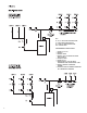
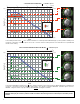
A
cross a Series
Loop System Using
Z
one Valves
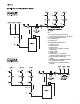
M
M
M
Across Multi-Zone
R
adiant Manifolds
with Loop Actuators
iSeries-R
B
C
A
B
C
A
MM MM MM MM
Outdoor
Sensor
Boiler
S
ensor
Typical Variable Speed Applications:
•
Zone Valves
• Panel Radiation with
Thermostatic Valves
• Radiant Loops with
Actuators
- Varies speed to
maintain proportional
or constant pressure
differential (∆P)
WARNING: Disconnect power when servicing. CAUTION: Use flexible conduit only. Not for use with rigid conduit.
CAUTION: Do not use flat rubber gaskets. Only use O-ring gaskets provided or leaks may result. Warranty will be void.
WARNING: SERVICING OF DOUBLE-INSULATED APPLIANCES. A double-insulated appliance is marked with one or more of the following:
The words “DOUBLE INSULATION” or “DOUBLE INSULATED” or the double insulation symbol (square within a square). In a double-insu-
lated appliance, two systems of insulation are provided instead of grounding. No grounding means is provided on a double-insulated appli-
ance, nor should a means for grounding be added. Servicing a double-insulated appliance requires extreme care and knowledge of the
system, and should be done by qualified service personnel. Replacement parts for a double-insulated appliance must be identical to the
parts they replace.