
Wiring Guide

104
Instruction Sheet
Hydro Air Fan Controls
Operation HAFC101 and 201:
The Hydro Air Fan Control is an interface
between the thermostat and air handler. It
also has an isolated end switch to start the
boiler and/or pump. When the thermostat
calls for heat, the Fan Control energizes the
end switch relay and allows the fan to operate
at low speed when the water is above the
optional aquastat setting. When the thermo-
stat calls for cooling, the Fan Control energizes
the condenser and operates on high speed.
Additional HAFC201 Operations:
Selectable one, three or four minute delay on
fan operation in heating mode. Selectable
pump exercise activates circulator but does
not enable boiler contacts. Two minutes every
24 hours minimizes the chance of bacteria
build-up in an open loop system. Thirty sec-
onds every two weeks minimizes seasonal
start-up problems generally associated with
harsh water conditions. Optional aquastat or
thermostat can be connected to Freeze
Protection TT terminals to reduce the chance
of pipes freezing by energizing the pump dry
contacts (boiler contacts not activated.)
Switch Settings (HAFC201):
1 1 minute on fan delay, in heating mode
2 3 minute on fan delay, in heating mode
1&2 4 minute on fan delay, in heating mode
3 Pump dry contact activated for 2 min-
utes every 24 hours (boiler contacts not
activated)
4 Pump dry contacts activated for 30 sec-
onds every two weeks (boiler contacts
not activated)
External Diagnostics:
The external lights show full functionality of
the Hydro Air Fan Control. The green light
should always be on, indicating that power is
connected. Red lights indicate fan operation
for heating and cooling modes.
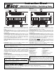
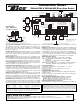
HAFC201-4
HYDRO AIR FAN CONTRL
THERMOSTAT
POWER
HEAT CALL
LED
INDICATORS
THERMOSTAT
T
CRWYG
AQUASTATS
TT
HAFC201-4
COOL FAN
HEAT FAN
BOILER
C
AIR HANDLER
XX
R
YG
L
G
H
WATER
COIL
FREEZE
PROT.
TT
XX
PUMP
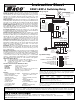
1 MIN FAN DELAY
3 MIN FAN DELAY
2MIN/24HR or 30SEC/2WK
PUMP EXERCISE
OFF ON
To: Optional
Aquastat on
Return Line of
Hydro Coil
To: Optional Aquastat
or Thermostat to sense
low ambient
temperature
Optional Power Wire
to Thermostat
that Requires 24VAC
NOTE: For 4 minute
ON DELAY of Heating Fan,
switch 1 and 3 MIN ON
DELAY to ON position.
FAN
RELAY
LINE
24 VAC
OUTDOOR
CONDENSER
UNIT
JUMPER
CIRCULATOR
(or to “T T” on
switching relay)
Dry Contacts To:
“T T” on Boiler
or Switching
Relay
H
N
120 VAC
INPUT
M
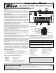
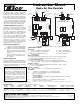
HAFC101-4
HYDRO AIR FAN CONTRL
THERMOSTAT
POWER
H2O COIL
LED
INDICATORS
CRWYG
AQUASTAT
T
T
HAFC101-4
HIGH FAN
LOW FAN
BOILER
C
AIR HANDLER
XX RYG
L
G
H
THERMOSTAT
T
To: Aquastat
on Return Line
of Hydro Coil
Optional Power Wire
to Thermostat
that Requires 24VAC
OUTDOOR
CONDENSER
UNIT
FAN
RELAY
LINE
24 VAC
LOW
HIGH
M
Dry Contacts To:
“T T” on Boiler
or Switching
Relay
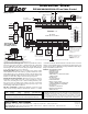
Terminal Description:
Thermostat:
C Optional: Common side of transformer W White - Heating signal
to power some styles of thermostats Y Yellow - Condenser signal
R Red - Hot side of transformer used to G Green - Fan signal
switch all functions
Water Coil Aquastat:
TT Connect to aquastat at air handler to control operation of the fan when
in the heating mode. Install a jumper if the aquastat is not used
Freeze Protection Aquastat:
TT Connect to aquastat or thermostat to sense low ambient temperature.
Reduces the chance of pipes freezing by energizing the pump dry contacts.
Pump Dry Contacts:
XX May switch pump directly by bringing in external line voltage or connect
to “T T” on a switching relay.
Boiler Dry Contacts:
XX Connect to the boiler or “T T” terminals on a switching relay.
Air Handler:
C Common side of transformer to power the Fan Control
R Red - Hot side of transformer used to switch all functions
Y Yellow - Condenser signal
One Speed Motor:
G
low
Connect the fan to the relay. Keep the jumper installed between G
high
and G
low
.
Two Speed Motor:
G
high
Remove jumper and connect G
high
to the high speed fan relay and
connect G
low
to the low speed fan relay.
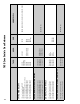
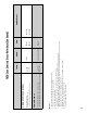
Specifications: ** Model number changed from SR501-F
PRODUCT NUMBER POWER INPUT MAXIMUM RELAY THERMOSTAT SINGLE PHASE MOTOR DIMENSIONS OF ENCLOSURE
NUMBER OF ZONES VOLTAGE COMBINED LOAD TYPE CURRENT RATING (RELAY) WIDTH HEIGHT DEPTH
HAFC101-4** 1 Zone 24 VAC Input5 amps DPDT .18 1/6 HP(5A) @120VAC 4 1/4" 5 1/4" 2 3/4"
HAFC201-4•• 1 Zone 24 VAC Input5 amps DPDT .18 1/6 HP(5A) @120VAC 4 1/4" 5 1/4" 2 3/4"
The Hydro Air Fan Controls are relay type DPDT, have a thermostat current of .18 and a single phase motor rating per zone of 1/6 HP (5A) @ 120 VAC.
* Both HAFC101 and 201 capable of 1 and 2 speed applications
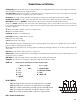
WARNING: Wiring connections must be
made in accordance with all applicable elec-
trical codes. Use copper wire only. 120 VAC
wiring must have a minimum temperature
rating of 75°C. Failure to follow this instruc-
tion can result in personal injury or death
and/or property damage. 12-18 gauge wire
recommended for 120 VAC connections,
14-22 gauge wire for thermostat connec-
tions, and 14-22 gauge wire for 24 VAC
source connections.
This device complies with part 15 of the FCC Rules. Operation is subject to the following two conditions: (1) This device may not cause harmful interference, and (2) this device must accept any inter-
ference received, including interference that may cause undesired operation.
Do it Once. Do it Right.
®
TACO, INC., 1160 Cranston Street, Cranston, RI 02920 Telephone: (401) 942-8000 FAX: (401) 942-2360.
TACO (Canada), Ltd., 8450 Lawson Road, Unit #3, Milton, Ontario L9T 0J8. Telephone: 905/564-9422. FAX: 905/564-9436.
Visit our web site at: http://www.taco-hvac.com
Printed in USA
Copyright 2010
TACO, Inc.