
Wiring Guide


103
Instruction Sheet
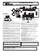
ZVC404-EXP & ZVC406-EXP Zone Valve Control
1234
ZONE 1
1234
ZONE 2
1234
ZONE 3
1234
ZONE 4
1234
ZONE 5
1234
ZONE 6
PRIORITY
ZONE
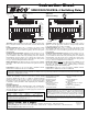
2 WIRE ZONE VALVE
(NO END SWITCH)
MUST USE JUMPER
TACO
3 WIRE
ZONE VALVE
1
2
3
JUMPER
3 & 4
MOTOR END
SWITCH
4 WIRE ZONE VALVE
(POWER OPEN,
SELF CLOSING)
JUMPER
3 & 4
SEE NOTE
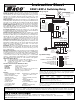
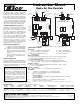
ZVC 406-EXP-4
SIX ZONE EXPANDABLE
ZONE VALVE CONTROL
24 VAC
FACTORY
INSTALLED
TRANSFORMER
120 VAC
INPUT
WHITE
BLACK
POWER IN
24 VAC
24 VAC
FACTORY
INSTALLED
TRANSFORMER
120 VAC
INPUT
WHITE
BLACK
TO
CIRCULATOR
DRY
CONTACTS
N/O COM N/C
PUMP END
SWITCH
ZONE 6 PUMP
END SWITCH
SLAVE
PRIORITY ON
RESET
POST PURGE ON
PRIORITY PROTECTION ON
PUMP EXERCISE ON
30 SEC/2 WK
MASTER
OFF
NORMAL
OFF
OFF
OFF
4 MIN/24 HOUR
NOTE: When a circulator is used
on the priority zone instead of a
zone valve, jumper 3 and 4 of
the priority zone.
INDIRECT
WATER HEATER
AQUASTAT OR
THERMOSTAT
T STAT 1
VALVE 1
T STAT 2
VALVE 2
T STAT 3
VALVE 3
T STAT 4
VALVE 4
VALVE 5
T STAT 6
VALVE 6
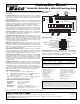
POWER
LED
INDICATORS
T STAT 5
TO: "TT" ON BOILER
TO: "TT" ON BOILER WITH
DHW "TT" INPUT
ZONE 1 ZONE 2
ZONE 3
ZONE 4 ZONE 5 ZONE 6 NET
EXPANSION
MAIN
PRIORITY
XX
XX
AB
CRW
CRW
CRW
CRW
CRW
CRW
C
12
END SWITCH THERMOSTATS (24 VAC) PRIORITY
24 VAC ZONE VALVES PRIORITY
XX
POWER
CONTROLS
ACCESSORY
PORT
FUSE
5 AMP
FUSE
5 AMP
THERMOSTATS (24 VAC)
Powered from Transformer A Powered from Transformer B
A
B
Powered from Transformer A Powered from Transformer B
Operation/External Diagnostics: When any thermostat calls for heat,
the appropriate zone valve is energized and the yellow light goes on.
When the zone valve is fully open, the red light goes on and energizes
the end switch relay. The green light should always be on, indicating
that power is connected.
Priority Operation: When the priority dip switch is set to ON and the
priority zone is actuated, all other zones will stop operation until pri-
ority zone is satisfied. When not switched to priority, all zones will
operate independently.
Mode Operation: When the dip switch is set to NORMAL, the end
switch relay will be energized if any zone is in operation. When the switch
is set to RESET, the end switch relay will only be energized if the priority
zone is in operation, or through the operation of a plug-in reset control.
Post Purge Operation: When the dip switch is set to ON, the priori-
ty zone output will stay energized for 2 minutes after its thermostat or
aquastat is satisfied, but not operate the boiler.
Priority Protection Operation: When the dip switch is set to ON, and
if the priority zone calls continuously for more than one hour, power
is returned to all the other zones, allowing each zone to function inde-
pendently. Once the priority zone is satisfied, the control's auto-reset is
activated and the priority zone is again allowed to have priority for up
to one hour starting from when it calls next.
Pump Exercise Operation: When the dip switch is set to ON, the solid
state timer cycles all the zone valves and circulating pumps that are
attached to the Expandable Zone Valve Control at the selected time
interval. The time interval can be set for the valves and pumps to run
for either 30 seconds every 2 weeks or for 4 minutes every 24 hours.
End Switches (Dry Contacts): The main end switch closes when any
zone thermostat calls for heat and the mode switch is set to NORMAL.
The main end switch also closes when the mode switch is set to RESET
and a PC Series boiler reset power control is calling for heat. The priority
end switch closes only when the priority zone thermostat or aquastat is
calling for heat.
Expansion Connections: Set the expansion switch to MASTER on the
switching relay that has the designated priority zone or is utilizing the
PC Series plug-in option. Set all other daisy chained controls to SLAVE.
Using thermostat wire (18-22 gauge) connect between terminals A, B,
C on the master control to the corresponding A, B, C on the SLAVE con-
trol(s). Controls may be daisy chained up to 20 zoning panels using any
combination of -EXP controls (120 zones if all are 6 zone panels).
Thermostat Input (24 vac):
R Hot side of transformer. Connect to R on thermostat.
W Switched R signal from thermostat. Connect to W on
thermostat.
C Common side of transformer. Connect to COM on
thermostat (optional).
NET Network terminals 1 & 2 are tied together for wiring convenience
when using communicating style thermostats (optional).
Power Input (120 vac):
Connect neutral (white) leads on transformers to 120 volts ac
neutral power supply.
Connect hot (black) leads on transformers to 120 volts ac
hot power supply.
Pump End Switch (Dry Contacts):
Connect hot power supply to the right side of the pump end switch
terminal on board.
Connect hot input lead of the circulator to the left side of the pump
end switch terminal on board.
Zone 6 Pump End Switches (Dry Contacts): See Diagram.
N/O Normally open terminal of the priority zone relay.
COM Common terminal of the priority zone relay.
N/C Normally closed terminal of the priority zone relay.
End Switch Pump Neutral Connections:
Connect neutral power supply directly to neutral lead on circulator(s).
WARNING: Wiring connections must be made in accordance with all
applicable electrical codes. Use copper wire only. 120 VAC wiring must have
a minimum temperature rating of 75°C. Failure to follow this instruction
can result in personal injury or death and/or property damage. 12-18 gauge
wire recommended for 120 VAC connections, 14-22 gauge wire for thermo-
stat connections, and 14-22 gauge wire for 24 VAC source connections.
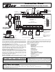
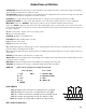
Wiring Diagram
N/O
COM
N/C
PUMP END
SWITCH
ZONE 6 PUMP
END SWITCH
XX
DHW
PUMP
SYSTEM PUMP AND BOILER TURN ON WHEN ANY ZONE VALVE OPENS.
DHW PUMP TURNS ON
ONLY WHEN PRIORITY ZONE CALLS.
SECONDARY PUMP COMES ON WHEN ANY ZONE CALLS EXCEPT PRIORITY ZONE.
SYSTEM
PUMP
SECONDARY
PUMP
120
VAC
HOT
NEUTRAL
Optional System
and/or DHW and/or
Secondary Circulators
This device complies with part 15 of the FCC Rules. Operation is subject to the following two conditions: (1) This device may not cause harmful interference, and (2) this device must accept any interference received, including interference that
may cause undesired operation.
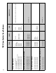
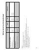
Specifications:
PRODUCT NUMBER INPUT MAX 24 VAC TYPE 1 ENCLOSURE
NUMBER OF ZONES VOLTAGE OUTPUT @ 25°C WIDTH HEIGHT DEPTH
ZVC406-EXP-4 6 with Priority 120/60/1 VAC, 3A 24 VA per Zone12
1
⁄
4
"8" 3"
40 VA per Transformer
The pump end switches are rated
1
⁄
6
hp, 5 amps at 120 VAC. The main and priority end switch connections
are rated 24 VAC, 1 amp. All thermostat and zone valve connections supply a 24 VAC class 2 output.
Do it Once. Do it Right.
®
TACO, INC., 1160 Cranston Street, Cranston, RI 02920 Telephone: (401) 942-8000 FAX: (401) 942-2360.
TACO (Canada), Ltd., 8450 Lawson Road, Unit #3, Milton, Ontario L9T 0J8. Telephone: 905/564-9422. FAX: 905/564-9436.
Visit our web site at: http://www.taco-hvac.com
Printed in USA
Copyright 2010
TACO, Inc.