
Wiring Guide

Do it Once. Do it Right.
®
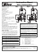
TACO, INC., 1160 Cranston Street, Cranston, RI 02920 Telephone: (401) 942-8000 FAX: (401) 942-2360.
TACO (Canada), Ltd., 8450 Lawson Road, Unit #3, Milton, Ontario L9T 0J8. Telephone: 905/564-9422. FAX: 905/564-9436.
Visit our web site at: http://www.taco-hvac.com
Printed in USA
Copyright 2010
TACO, Inc.
98
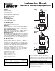
SR501-OR-4 Switching Relay Instruction Sheet (page 4)
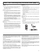
TROUBLESHOOTING:
Step Five:
As in any troubleshooting procedure, it is important to isolate a prob-
lem as much as possible before proceeding. The blinking error LED
light greatly simplifies troubleshooting of the SR501-OR. If you sus-
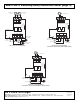
pect a wiring fault, return to step three and carefully check all external
wiring and wiring connections.
Sensor Errors:
• If an outdoor sensor fault occurs, the SR501-OR will assume a
fixed outdoor temperature of 32°F (0°C) and will target the
appropriate supply water temperature. The Boiler light will blink
twice every 5 seconds to indicate the outdoor sensor error.
• If a boiler sensor fault occurs, the SR501-OR turns the boiler off
and the Boiler light will blink once every 5 seconds to indicate
the boiler supply sensor error.
Adjustment of Settings:
• If the outdoor temperature is cold and the rooms are cold,
increase the Outdoor Design setting by 5°F (3°C) per day.
• If the boiler is cycling too often, increase the Differential setting.
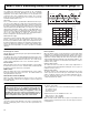
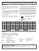
Testing the Sensors:
A good quality test meter capable of measuring up to 5,000 kΩ
(1 k = 1000 Ω) is required to measure the sensor resistance. In addition
to this, the actual temperature must be measured with either a good
quality digital thermometer, or, if a thermometer is not available, a sec-
ond sensor can be placed alongside the one to be tested and the read-
ings compared. First measure the temperature using the thermometer
and then measure the resistance of the sensor at the control. The wires
from the sensor must not be connected to the control while the test is
performed. Using the chart below, estimate the temperature measured
by the sensor. The sensor and thermometer readings should be close.
If the test meter reads a very high resistance, there may be a broken
wire, a poor wiring connection or a defective sensor. If the resistance is
very low, the wiring may be shorted, there may be moisture in the sen-
sor or the sensor may be defective. To test for a defective sensor, mea-
sure the resistance directly at the sensor location.
Ω
Ω
Do not apply voltage to a sensor at any time
as damage to the sensor may result.
Temperature Resistance Temperature Resistance Temperature Resistance Temperature Resistance
°F °C Ω°F °C Ω°F °C Ω°F °C Ω
-30
-20
-10
0
10
20
30
40
50
60
70
80
90
100
110
120
130
140
150
160
170
180
190
200
-34
-29
-23
-18
-12
-7
-1
4
10
16
21
27
32
38
43
49
54
60
66
71
77
82
88
93
234,196
165,180
118,018
85,362
62,465
46,218
34,558
26,099
19,900
15,311
11,883
9,299
7,334
5,828
4,665
3,760
3,050
2,490
2,045
1,689
1,403
1,172
983
829
TECHNICAL DATA:
The installer must ensure that this control and its wiring are isolated
and/or shielded from strong sources of electromagnetic noise.
This
device complies with part 15 of the FCC Rules. Operation is subject to the
following two conditions: (1) This device may not cause harmful interfer-
ence, and (2) this device must accept any interference received, including
interference that may cause undesired operation.
SR501-OR Boiler Reset Control Relay:
Control: Microprocessor PI control. This is not a
safety (limit) control.
Dimensions: 4
1
⁄
4
" W x 5
1
⁄
4
" H x 2
3
⁄
4
" D
Approvals: UL listed for US and Canada, Temperature
Indicating and Regulating Equipment.
Power Supply: 120/60/1 VAC, 12 amps maximum
Relays: Boiler Relay 1 amp @ 24 VAC
Circulator Relay
1
⁄
3
HP (6 FLA, 36 LRA
Sensors: NTC thermistor, 10 kΩ @ 77°F
(25°C ±0.2°C) ß=3892
Outdoor Design Temp.: -30°F to 40°F (-35°C to 5°C)
Boiler Minimum: 70°F or 140°F (21°C or 60°C)
Differential: 10°F or 20°F (6°C or 12°C)
WWSD: 70°F (21°C)