
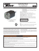
Install Instructions
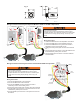

Alternate Wiring:
Wiring Instructions
1. Connect the WHITE wire to the transformer's common
connection.
2. Connect the RED wire to the transformer's hot output.
3. Connect the GREEN wire to a ground source that is
electrically common to the boiler ground.
4. Cut off the quick connectors from both YELLOW wires and
strip the wire ends.
5. Open the connection to the other limit controls
ahead of the rst limit control.
6. Wire the YELLOW leads as shown to connect the LTR's
relay in series and ahead of all other limit controls.
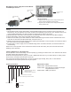
24VAC Systems
LTR024 Models Only
24 VAC Class 2
Transformer
120 VAC
HOT
COMMON
24 VAC
GREEN
WHITE
RED
YELLOW
YELLOW
Limit
Controls
Gas
Valve
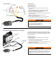
Wiring Boilers with an Integrated Control Module:
On boilers equipped with a United Technologies integrated
boiler control module, Taco recommends the use of the "Boiler
Module Wiring Harness". This harness is available from Taco,
Part 9300-2715RP.
Wiring Instructions
1. Disconnect the boiler wire harness from the integrated
control module.
2. Plug the boiler wire harness connector into the female
connector on the LTR wiring harness.
3. Plug the male connector on the LTR wiring harness into the
integrated control module.
4. Plug boiler module module wiring harness into LTR.
Integrated Boiler
Control
Male
Connector
Female
Connector
Boiler Module
Wiring Harness
1
3
2
4
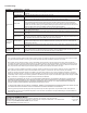
• Shock hazard. Disconnect power source before servicing. Serious
injury or death could result.
• Only use the wiring harness supplied with the control or factory
supplied alternates. Use of other wire harnesses or insulation types
could result in re causing property damage, serious injury, and
death.
• Shock hazard. Disconnect power source before servicing. Serious
injury or death could result.
• Never connect 120VAC to Red/White leads.
• Only connect 120VAC to Yellow leads.
• Misapplication of 120VAC will damage control.
Factory Wiring