
Install Instructions
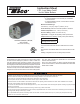

Service LED
(Amber)
Test/Reset
Button
2-3 Wraps Teon®
Tape
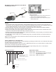
Item Description
Status LED Bi-color LED status indicator. See "LED States" table for details.
Service LED Amber LED indicator that service is needed on LTR or system.
Test Button Push button switch for testing safety shutdown of boiler controls.
LTR Connector Power and relay contact connector.
Reset Button Manual Reset when pressed after water returns to safe level
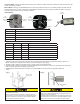
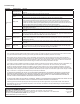
Status LED Service LED Contacts Meaning
Green Off Closed Normal
Green Amber Closed Safe water level, weak probe signal - Service soon.
Red Off Open Low water condition, (LW)
Red Amber Open Probe signal too weak, LW condition - Service now.
Blinking Red Off Open Control failure. Lockout in LW condition.
Off Off Open No power to LWCO.
Off Off Open Test Button Pressed in Manual Mode, LW condition
LED States:
Installation:
1. Install the probe above the minimum safe water level, as determined from the boiler manufacturer's literature. (See Fig. 1)
NOTE: This may be in a tapping on the boiler or in the boiler supply or return piping.
2. Install the probe to extend into the boiler cavity or piping to make contact with the water.
3. Install the probe so that the exposed portion of the stainless steel is a minimum of 1/4" from any grounding surface inside the
boiler (to prevent the probe from shorting). (See Fig. 2)
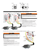
4. Hand tighten the LTR into the process connection. Do not cross-thread. Do not use a wrench or other tools to tighten the
control.
Automatic Model: Pressing the TEST button with the LTR in a Normal condition with water covering the probe will cause the LTR
to enter a Low Water Condition.
Manual Model: Pressing the TEST/RESET button for two seconds while the LTR is in a Low Water Condition will reset the LTR
provided water covers the probe. Pressing the TEST/RESET button with the LTR in a Normal condition with water covering the
probe will cause the LTR to enter a Low Water Condition.
• Do not mount device with probe angled upward or deposits can
accumulate on the probe.
• Mount only with probe facing horizontally or vertically downward
and maintain 1/4" minimum clearance from electrode and pipe wall.
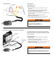
• Failure to install probe as directed can cause improper operation
and damage to equipment and property.
• Apply Teon® tape only to the threads of the LTR. Do not use pipe
dope or other thread sealants. Damage to the control may occur
and result in improper operation.
• Hand tighten the LTR into the process connection being careful to not
cross-thread. Do not use a wrench or other tools to tighten the control.
Damage to the control may occur and result in improper operation.
Fig. 2
LTR
Connector
LTR
Connector
Status LED
(Bi-color)
Status LED
(Bi-color)
Service LED
(Amber)
Test
Button
Probe
Process
Connection
Minimum Safe
Water Level
LTR Features:
Fig. 1