
Brochure

Heat Motor Zone Valves
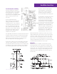
Zone Valve Operation and Wiring
There have always been questions
surrounding how the 3-wire terminal
block design of the Taco Heat Motor
Zone Valve works. The explanation
below and associated diagrams explain
step-by-step the operation of the
zone valve.
As the air temperature at the
thermostat drops to the thermostat
setting, a normally open contact in
the thermostat closes. This completes
a circuit between the thermostat, the
zone valve transformer and the heat
motor of the zone valve power head
(terminals 1 and 2). 24 VAC now flows
through the wires wrapped around
the heater section of the element
inside the zone valve heat.
The expandable wax substance inside the element is heated.
It expands and pushes the piston inside the element down
against the valve stem. Since the valve is an upside down
globe valve, this downward push on its stem moves the
valve disc away from its seat, opening the valve.
As the piston continues to move down, further opening the
valve, the contacts inside the enclosed end switch close as
the actuator tab attached to the piston moves away from the
end switch. This dry contact end switch closure completes
the circuit through terminals 2 and 3 of the power head to
the boiler control (T T) and separate
system transformer. The relay in the
boiler (or zone control box) starts the
circulator. The piston continues to
move down until the valve is fully open.
An interruption of current to the power
unit heater occurs in the fully open
mode because the outer blade of the
heater switch is deflected causing the
heater element to open, interrupting
the 24 VAC power from flowing through
the heater wires. As the piston retracts
slightly, the contacts on the heater
switch meet again, resuming power to
the heater wires wrapped around the
wax filled element. This slight back
and forth motion is repeated as long
as the thermostat contact is closed.
When the thermostat is satisfied, its contacts open and cut
off the 24 VAC power to the power head. The wax inside the
element cools and contracts. The force of the valves spring
moves the valve disc up against the valve seat. Hence the
valve stem also moves up, pushing the piston back into the
element. Now that the heater switch is closed, the snap-acting
end switch between terminals 2 and 3 is open.
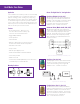
Wiring Note
While two circuits, each with its own transformer, touch
at terminal #2, they do not communicate or interfere with
each other in any way (see figure C). Each circuit flows only
in that circuit. This occurs because the transformer in either
circuit cannot cause a voltage or current driving force to be
realized in the other circuit when joined only at one point
to that circuit.
Figure C: Zone Valve Circuits.