
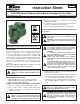
Install Instructions

1. Using teflon tape or high quality thread sealant, install
T
aco companion flanges on threaded pipe ends to
ensure proper fit-up and leak protection.
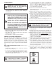
2. Minimize pipe strain on pump by using pipe hangers on
the suction and discharge lines.
3. Position vertical and horizontal piping so bolt-holes on
pump and companion flanges match. Do not force the
suction and discharge lines into position. This may cre-
ate excess stress on the pump casing and flanges.
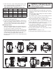
B. Mounting Position:
• Always install pump with the motor shaft in the horizon-
tal position and the capacitor/conduit box oriented on
top of the motor housing, as shown in Fig. 1.
• Standard pump body mounting position is with the flow
in the up-discharge direction (body position #3). The
pump body may be field-rotated in any direction to
accommodate system piping and flow direction.
• Be sure to align the arrow on the casing with desired
flow direction.
C. Electrical Wiring:
• All electrical wiring must be installed by a licensed elec-
trician in accordance with local and national codes and
regulations.
•Electrical supply and grounding wires must be suitable
for at least 90ºC (194ºF).
• Wood Boiler Series circulators are thermally protected
and do not require external overload protection.
1. Be sure all electrical power to pump is disconnected
and locked-out before proceeding with wiring.
2. Loosen capacitor/conduit box screw and remove cover.
3. Attach appropriate size connector to one of the two
knock-out holes in the capacitor/conduit box.
4. Using minimum 18 AWG wire, connect the hot and neu-
tral leads from the electrical supply to the respective
black and white leads in the capacitor box.
5. Connect the ground wire to the green ground screw in
the capacitor box.
6. Replace capacitor/conduit box cover.
7. Insert plastic plug provided in unused knock-out hole.
FLOW
NOT RECOMMENDED
RECOMMENDED
FLOW
FLOW
FLOW
CAUTION: Do not support, suspend or brace
pump motor or early failure may result.
Support provided by casing is sufficient for
structural integrity of pump
Fig. 1 – Installation Positions
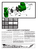
CONNECTION
3
⁄4" 1" 1
1
⁄4" 1
1
⁄2"
Iron NPT
110-251F 110-252F 110-253F 110-254F
Stainless
Steel NPT
110-251SF 110-252SF 110-253SF 110-254SF
B
ronze SWT
110-523BSF 110-524BSF 110-525BSF 110-526BSF
Shut-Off NPT
SF-075T SF-100T SF-125T SF-150T
Shut-Off SWT
SF-075S SF-100S SF-125S SF-150S
WOOD BOILER SERIES COMPANION FLANGE SETS