
Brochure


8.
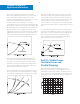
From a practical point of view, the shutoff head should be
5 to 10 percent higher than the static head because the
slightest reduction in pump head (such as that caused by
possible impeller erosion or lower than anticipated motor
speed or voltage) would again cause shutoff head to be
lower than static head. If the pump is properly selected,
there will be only one resistance curve intersection with
the pump curve and definite, unchanging flow will be
established, as shown in Fig. 3–4.
Pumps Operating In Parallel
In more complex piping systems, two or more pumps
may be arranged for parallel or series operation to meet a
wide range of demand in the most economical manner.
When demand drops, one or more pumps can be shut
down, allowing the remaining pumps to operate at peak
efficiency. Pumps operating in Parallel give multiple flow
capacity against a common head. When pumps operate
in series, performance is determined by adding heads at
the same flow capacity. Pumps to be arranged in series
or parallel require the use of a system curve in conjunc
-
tion with the composite pump performance curves to
evaluate their performance under various conditions.
It is sometimes heard that for multiple pumping the
individual pumps used must be stable performance
curves. Correctly designed installations will give trou
-
ble-free
service with either type of curve, however.
The important thing to remember is that additional
pumps can be started up only when their shutoff heads
are higher than the head developed by the pumps
already running.
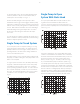
If a system with fixed resistance (no throttling devices
such as modulating valves) is designed so that its head,
with all pumps operating (maximum flow) is less than the
shutoff head of any individual pump, the different pumps
may be operated singly or in any combination, and any
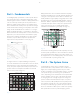
starting sequence will work. Fig. 3–5 shows and example
consisting of two dissimilar unstable pumps operating on
an open system with static head.
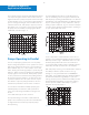
It is also important to realize that stable curves do not
guarantee successful parallel pumping by the mere fact
that they are stable. Fig. 3–6 illustrates such a case. Two
dissimilar pumps with stable curves are installed in a
closed system with variable resistance (throttling may be
affected by manually operated valves, for example).
With both pumps running, no benefit would be obtained
from Pump 1 with the system resistance set to go
through A, or any point between 0 and 100 GPM, for
that matter. In fact, within that range, fluid from Pump 2
would flow backward through Pump 1 in spite of its
running, because pressure available from Pump 2 would
flow backward through Pump 1 in spite of its running,
because pressure available from Pump 2 is greater
than that developed by Pump 1.
4
4
3
Fig. 3-4
Fig. 3-5
6
6
3
Fig. 3-6
5
5
3
Commercial Hydronic
Application Information