
Brochure


7.
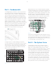
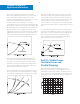
So-called unstable curves are those with maximum head
not at zero, but at 5 to 25 percent of maximum flow, as
shown by the curve for Pump 1 in Fig. 3 – 1.
The term unstable, though commonly used, is rather
unfortunate terminology in that it suggests unstable pump
performance. Neither term refers to operating characteristic,
however. Each is strictly a designation for a particular shape
of curve. Both stable and unstable curves have advantages
and disadvantages in design and application. It is left to
the discretion of the designer to determine the shape
of his curve.
In a vast majority of installations, whether the pump curve is
stable or unstable is relatively unimportant, as the following
examples of typical applications show.
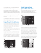
Single Pump In Closed System
In a closed system, such as a Hydronic heating or cooling
system, the function of the pump is to circulate the same
quantity of fluid over and over again. Primary interest is in
providing flow rate. No static head or lifting of fluid from
one level to another takes place.
All system resistance curves originate at zero flow any head.
Any pump, no matter how large or small, will produce some
flow in a closed system.
For a given system resistance curve, the flow produced by
any pump is determined by the intersection of the pump
curve with the system resistance curve since only at this
point is operating equilibrium possible. For each combina
-
tion of system and pump, one and only one such intersec-
tion exists. Consequently, whether a pump curve is stable
or unstable is of no consequence. This is illustrated in
Fig. 3 –1.
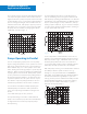
Single Pump In Open
System With Static Head
In an open system with static head, the resistance curve
originates at zero flow and at the static head to be
overcome. The flow is again given by the intersection of
system resistance and pump curves as illustrated for a stable
curve in Fig. 3–2.
It has been said that in an open system with static head a
condition could exist where an unstable curve could cause
the flow to “hunt” back and forth between two points since
the system resistance curve intersects the pump curve
twice, as shown in Fig. 3–3. The fallacy of this reasoning
lies, in the fact that the pump used for the system in Fig.
3–3 already represents an improper selection in that it can
never deliver any fluid at all. The shutoff head is lower than
the static head. The explanation for this can be found in the
manner in which a centrifugal pump develops its full pres
-
sure when the motor is started. The very important fact to
remember here is that the shutoff head of the pump must
theoretically always be at least equal to the static head.
Fig. 3-1
2
2
3
Fig. 3-2
3
3
3
Fig. 3-3