
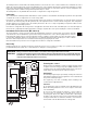
Install Instructions

6
Temperature Resistance Temperature Resistance Temperature Resistance Temperature Resistance
°F °C °F °C °F °C °F °C
-30
-20
-10
0
10
20
30
40
50
60
70
80
90
100
110
120
130
140
150
160
170
180
190
200
-34
-29
-23
-18
-12
-7
-1
4
10
16
21
27
32
38
43
49
54
60
66
71
77
82
88
93
234,196
165,180
118,018
85,362
62,465
46,218
34,558
26,099
19,900
15,311
11,883
9,299
7,334
5,828
4,665
3,760
3,050
2,490
2,045
1,689
1,403
1,172
983
829
Troubleshooting
As in any troubleshooting procedure, it is important to isolate a problem as much as possible before proceeding. The error messages
greatly simplify troubleshooting of the 00-VT. When the 00-VT flashes an error message, identify the fault and follow standard testing
procedures to confirm the problem. If you suspect a wiring fault, return to the wiring section on this brochure and carefully check all
external wiring and wiring connections.
For your safety and protection of permanent damage to the microprocessor, the 00-VT includes a 2.5 A 250 V (ac) field replaceable fuse.
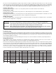
Testing The Sensors
A good quality test meter capable of measuring up to 5,000 kΩ (1 kΩ = 1000 Ω) is required to measure the sensor resistance. In
addition to this, the actual temperature must be measured with a good quality digital thermometer.
First measure the temperature using the thermometer and then measure the resistance of the sensor at the 00-VT. The wires from the
sensor must not be connected to the PC Board while this test is performed. The wiring terminals are easily removed by pulling them
from the PC Board. Using the chart below, estimate the temperature measured by the sensor. The sensor and thermometer readings
should be close. If the test meter reads a very high resistance, there may be a broken wire, a poor wiring connection or a defective
sensor. If the resistance is very low, the wiring may be shorted, there may be moisture in the sensor or the sensor may be defective.
To test for a defective sensor, measure the resistance directly at the sensor location.
WARNING: Do not use in swimming pool or spa areas; pump has not been investigated for this application.
WARNING In the event the retaining screws have been pulled out of the housing, DO NOT replace them. Use of any
other screw may short out the stator windings, creating a risk of electrical shock.
CAUTION: When installing electrical connections, do not apply mechanical loads to the capacitor box; otherwise,
retaining screws may be pulled out of the housing, making circulator unusable.
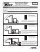
The sensors can be strapped directly to the pipe using a cable tie. Insulation should be placed around the sensor to reduce the effect
of air currents on the sensor measurement. The sensors should be placed downstream of a pump or after an elbow or similar fitting.
This is especially important if large diameter pipes are used because the thermal stratification within the pipe can result in erroneous
sensor readings. Proper sensor location requires that the fluid is thoroughly mixed within the pipe before it reaches the sensor.
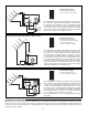
Collector Sensor (Src)
Connect the two wires from the collector sensor (Src) directly into the Com and Src terminals on the PC Board.
Storage Sensor 1 (Tnk)
Connect the two wires from the primary storage tank sensor (Tnk) directly into the Com and Tnk terminals on the PC Board.
Storage Sensor 2 (Hol)
Connect the two wires from the second storage tank sensor (Hol) directly into the Com and Hol terminals on the PCB. The second
storage tank sensor is only operational when the control is configured for 2 storage tanks.
Holiday Feature (Hol)
To enable the holiday feature, short directly into the Com and Hol terminals on the PC Board. The Holiday feature is only available
when the control is configured for 1 storage tank.