
00 Series Zoning Circulator Pump Instruction Manual
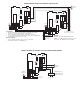

Line Voltage – Connect 115VAC to HOT(H) and NEUTRAL(N)
terminals.
Priority Switch – Connect (P) to (P) of next circulator. Repeat
step until all Zoning Circulator (P) to (P) connections are
made.
Non-Priority – If the Priority feature is not used, do not con-
nect the (P) terminals between circulators.
Ground – Provide the proper ground connection wire and
attach it to the green ground screw inside the circulator’s
capacitor box.
Specifications:
Terminals R & W:
Thermostat – 24VAC SPDT 2 wire heating thermostat, or Di-
gital Electronic 2 wire 24VAC thermostat with a maximum
current draw of 30 milliamps.
Anticipator Setting – 0.20.
Cycles –Too frequent, adjust upward. Too long, adjust down-
ward.
Terminals X & X:
Relay – Dry Contact Switch Ratings
• 24VAC 1 Phase 3 Amps
Terminals R & C:
Optional Outputs
• 24VAC 0.5 VA max
Terminal P:
Priority Connection
• 120VAC output when “MASTER” switch is “ON”
• 120VAC input when
“
MASTER” switch is “OFF”
Terminals N & H:
• 120VAC 8 Amp in-rush current max
Testing Sequence:
1. Restore Electrical Power.
2. Turn room thermostat “ON”.
3. Circulator will start:
• Green LED light turns “ON”
• Relay-contact will close between terminals X & X
Testing Priority Switch:
1. Turn Priority Circulator room thermostat “ON”.
2. Priority Circulator Starts:
• Green LED light turns “ON”
• Relay-contact will close between terminals X & X
• All Non-Priority circulators will turn “OFF”.
3. Priority Circulator room thermostat turns “OFF”.
• Priority Circulator stops.
• Any Non-Priority Circulators will now begin to operate.
PC Board Replacement Kits
005-029RP Models: 003, 005, 006, 007, 008
009-034RP Models: 009, 0010, 0011, 0012, 0014
0013-018RP Models: 0013 only
PNH
HIGH VOLTAGE
TERMINAL STRIP