
Install Instructions

6
Temperature Resistance Temperature Resistance Temperature Resistance Temperature Resistance
°F °C °F °C °F °C °F °C
-30
-20
-10
0
10
20
30
40
50
60
70
80
90
100
110
120
130
140
150
160
170
180
190
200
-34
-29
-23
-18
-12
-7
-1
4
10
16
21
27
32
38
43
49
54
60
66
71
77
82
88
93
234,196
165,180
118,018
85,362
62,465
46,218
34,558
26,099
19,900
15,311
11,883
9,299
7,334
5,828
4,665
3,760
3,050
2,490
2,045
1,689
1,403
1,172
983
829
WARNING: Do not use in swimming pool or spa areas; pump has not been investigated for this application.
WARNING: In the event the retaining screws have been pulled out of the housing, DO NOT replace them.
Use of any other screw may short out the stator windings, creating a risk of electrical shock.
CAUTION: When installing electrical connections, do not apply mechanical loads to the capacitor box;
otherwise, retaining screws may be pulled out of the housing, making circulator unusable.
Troubleshooting
As in any troubleshooting procedure, it is important to isolate a problem as much as possible before proceeding. The error messages
greatly simplify troubleshooting of the 00-VS. When the 00-VS flashes an error message, identify the fault and follow standard testing
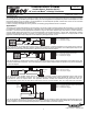
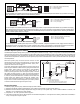
procedures to confirm the problem. If you suspect a wiring fault, return to the wiring section on this brochure and carefully check all
external wiring and wiring connections.
For your safety and protection of permanent damage to the microprocessor, the 00-VS includes a 2.5 A 250 V (ac) field replacable fuse.
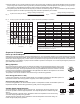
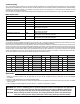
Testing The Sensors
A good quality test meter capable of measuring up to 5,000 kΩ (1 kΩ = 1000 Ω) is required to measure the sensor resistance. In addi-
tion to this, the actual temperature must be measured with a good quality digital thermometer.
First measure the temperature using the thermometer and then measure the resistance of the sensor at the 00-VS. The wires from the
sensor must not be connected to the PC Board while this test is performed. The wiring terminals are easily removed by pulling them
from the PC Board. Using the chart below, estimate the temperature measured by the sensor. The sensor and thermometer readings
should be close. If the test meter reads a very high resistance, there may be a broken wire, a poor wiring connection or a defective
sensor. If the resistance is very low, the wiring may be shorted, there may be moisture in the sensor or the sensor may be defective.
To test for a defective sensor, measure the resistance directly at the sensor location.
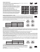
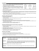
LED LED Status 00-VS Status
PWR Solid Power On
HEAT REQ Solid Heat Request
% OUT Flash (Solid) Variable Speed Output (100% Speed)
RED OUT Solid Reduced Output (boiler protection activated)
HEAT REQ Flash System Sensor S1 Fault.
00-VS does not operate
RED OUT Flash System Sensor S2 Fault.
00-VS does not operate
HEAT REQ and RED OUT Flash Boiler Sensor S3 Fault.
00-VS does not provide boiler protection.
PWR, HEAT REQ and RED OUT Flash No sensors connected, or incompatible mode and sensor combination.
00-VS does not provide boiler protection.
Multi-Status LEDs
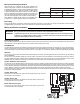
Application
1. Maximum operating pressure: 125 psi (862 kPa) on all “00” Series Circulators, 200 psi (1379 kPa) on all Load Match®
Circulators.
2. Maximum water temperature not to exceed nameplate rating.
3. Cast iron circulators are to be used for closed loop systems. Bronze circulators are to be used for open loop, fresh water, or potable
water systems.
4. Taco Cartridge circulator pumps are for indoor use only – employer uniquement a l´interieur.