
Install Instructions

2
Collector
Sensor
P1P2
Tank
Sensor
Solar Collector
Collector
Sensor
Tank
Sensor
Limit
shut-off request
Heat Sink
(Pool H/X,
Earth, etc.)
Solar Collector
P1
R1
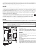
SEQUENCE OF OPERATION
Whenever the 00-VT is powered up, the green PWR LED turns on and operates to maintain a setpoint temperature difference (delta T)
between a heat source (solar collector) and a heat sink (storage tank). The percent output (% OUT) LED flashes at different rates based
on the speed of the collector pump. As the % OUT LED flashes faster it indicates a faster speed of the pump. A fully on LED indicates
the pump is at 100% capacity.
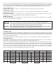
Essential Switch Settings
5 = OFF (Single Storage Tank)
2 = ON, 1 = OFF (Collector Sink)
Essential Switch Settings
5 = OFF (Single Storage Tank)
4 = OFF (Freeze Protection Inactive)
3 = ON (Drainback Active)
2 = ON, 1 = ON (Booster Pump)
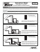
00-VT-4: Single Storage Tank, Auxiliary Heat Sink
00-VT-5: Single Storage Tank, Drainback, Booster Pump
The 00-VT adjusts the variable speed output to the collector pump
P1 to maintain a setpoint temperature difference (ΔT) between
the collector sensor and the tank sensor. An auxiliary heat sink
is included to accept heat in the event both the storage tank and
the collector become too hot. During this condition, the diverting
valve operates and the collector pump runs at full speed to transfer
heat from the collector to the auxiliary heat sink.
The 00-VT adjusts the variable speed output to the collector pump
P1 to maintain a setpoint temperature difference (ΔT) between
the collector sensor and the tank sensor in a drainback system.
A booster pump is included in order to provide the necessary
head requirements on startup to fill the system. When operation
is required, the control turns on the booster pump and operates
the collector pump at full speed for 3 minutes. After the 3 minute
period elapses, the booster pump turns off and the collector pump
operates to maintain the setpoint temperature difference. When
operation is not required, the control turns off the collector pump
draining the fluid back into the drainback tank.
Collector
Sensor
Primary
Tank
Sensor
Auxiliary
Tank
Sensor
Solar Collector
P1
R1
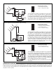
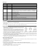
Essential Switch Settings
5 = ON (Two Storage Tanks)
2 = ON, 1 = OFF (Collector Sink)
00-VT-6: Two Storage Tanks
The 00-VT adjusts the variable speed output to the collector pump
P1 to maintain a setpoint temperature difference (ΔT) between the
collector sensor and the primary storage tank sensor. The control
considers operation including a second storage tank. In this case,
the control operates the diverting valve and adjusts the variable
speed output to the collector pump P1 to maintain a setpoint tem-
perature (ΔT) between the collector sensor and the auxiliary tank
sensor. Priority is given to the primary storage tank.
Note: An additional tank sensor is required (Taco part number
9300-2044).