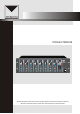
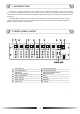
OPERATION MANUAL PROJECTMIX818 ZONE 1 SOURCE UP SOURCE DOWN PAGE BUSYMIC1 PRIORITY ZONE 2 SOURCE UP SOURCE DOWN PAGE BUSY MIC1 PRIORITY ZONE 3 SOURCE UP SOURCE DOWN PAGE BUSY MIC1 PRIORITY ZONE 4 SOURCE UP SOURCE DOWN PAGE BUSY MIC1 PRIORITY ZONE 5 SOURCE UP SOURCE DOWN PAGE BUSY MIC1 PRIORITY ZONE 6 SOURCE UP SOURCE DOWN PAGE BUSY MIC1 PRIORITY ZONE 7 SOURCE UP SOURCE DOWN PAGE BUSY MIC1 PRIORITY ZONE 8 SOURCE UP SOURCE DOWN PAGE BUSY MIC1 PRIORITY MIC 1 MIC 1 MIC 1 MIC
SAFETY PRECAUTIONS Be sure to read the instructions in this section carefully before use. Make sure to observe the instructions in this manual as the conventions of safety symbols and messages regarded as very important precautions are included. We also recommend you keep this instruction manual handy for future reference.
SAFETY PRECAUTIONS When Installing the Unit Never plug in nor remove the power supply plug with wet hands, as doing so may cause electric shock. When unplugging the power supply cord, be sure to grasp the power supply plug; never pull on the cord itself. Operating the unit with a damaged power supply cord may cause a fire or electric shock. When moving the unit, be sure to remove its power supply cord from the wall outlet.
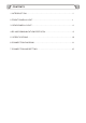
CONTENTS 1.INTRODUCTION ................................................................................................ 1 2.FRONT PANEL LAYOUT................................................................................... 1 3. REAR PANEL LAYOUT..................................................................................... 4 4.RS 485 COMMUNICATION PROTOCOL ........................................................ 9 5. SPECIFICATIONS .................................................................
1. INTRODUCTION The matrix & paging controller family comprise an 8 channel and 4 channel ones which are cater for multi-zone ,paging andmulti-soucres selection system .They are complete solution for multi-zone, multi-functional venues like entertainment places, large hotel,sport or grm centers,shopping mall and airport ect. PROJECTMIX818 offer direct connection of up 8music source input ,8remote control panels.
FRONT PANEL LAYOUT 1. Source Select The source select button (1) is used to select the source for the zone. Each zone has a separate source selection button. There are 9 selectable sources: Line sources 1 through 8 and a local Microphone source.A different local source (remote in wall mixer or source select/volume control)can beconnected to each zone. A zone cannot select the local source connected to another zone.Pressing the source select button will cycle through all zones 5.
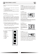
FRONT PANEL LAYOUT 9. Monitor ZONE SELECT The ZONE SELECT button (9) is used to select one of the 8 zones to be monitored.Pressing the zone select button will cycle through allzones in sequence as follows:1,2,3,4, 5,6, 7, 8, and OFF. A zone can be selected pressing the ZONE SELECT button.Once the display shows the desired zone, press the ENTER button to confirm and change to the selected zone. 12. Monitor Volume The Monitor Volume control knob (12) will control the in-built Monitor Speaker volume level.
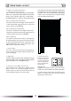
3. REAR PANEL LAYOUT OUTPUT + 3 - 0.775V/600 GAIN + dB - GAIN + dB - GAIN + dB - GAIN + dB - GAIN + dB - +10 dB -10 HF +10 dB -10 HF +10 dB -10 HF +10 dB -10 HF +10 dB -10 HF +10 dB -10 LF +10 dB -10 LF +10 dB -10 LF +10 dB -10 LF +10 dB -10 LF +10 dB -10 LF +10 dB -10 LF +10 dB -10 PAGE + dB - PAGE + dB - GAIN G 2 G 2 0V 1 300mV-1.
REAR PANEL LAYOUT 2. EVAC / Fire System Interface (7 Way Pheonix Connector) PIN 1- [+24V DC 24V] Power supply input.(Battery Back Up or UPS)PIN 2- [GROUND DC 24V] Power Supply input .(Battery Back Up or UPS) PIN3 [COMMON],Which is Common for ALERT & EVAC The Matrix can be linked with a DB37 Cable.This will enable the Line I-8 Sources,MIC1 input,Paging Consoles I & 2 , and Communication Data of the master unit to be shared with any Slave Matrix Units connected to the system.
REAR PANEL LAYOUT Local zone source level has three adjustments, namely: 8. Page The Zone Page Output Volume Control will adjust the output paging level for the Zone.Every Zone has a Page Output Volume Control which enables the paging level of each zone to be set independently of other zones. a. Gain control for the local source Input on the rear of the Matrix b. A Music level control on the Matrix front panel or the remote wall control c. A Master level control on the Matrix front panel. 9.
REAR PANEL LAYOUT 12. HF The Zone HF Treble of the Zone Output can be controlled by adjusting the HF Treble Level The EMC Input will only take priorityand broad -cast to zones where there is a Zone FireAlarm Dry Contact Closure.Each zone has aseparate Fire Alarm Dry Contact.Fire alarm, alert,EVAC and EMC in are of equivalent priority. dB Control. This Level Control will provide adjustment of the 100Hz AudioFrequency by 10dB.
REAR PANEL LAYOUT 20. MIC1 Input The balanced MIC1 input XLR type has an impedance of 600ohms. Each zone has aMIC1 Priority Button. The Line Inputs have an impedance of 47 kohms. 1. Line 1-8 source inputs will be selectable using the Source Select control on the front of the Matrix. 2) 2. The selected source input number will be indicated on the Matrix zone display. 3. Any extension Matrix unit connected to the system will use sources line 1-8 from the master Matrix. 4.
4. RS 485 COMMUNICATION PROTOCOL Status Data To Paging Console RS 485 Communication Protocol After getting paging data from the remote paging console, the Matrix sends zone status data to the paging console in the following format: Baud Rate: 57600bps/S Parity Check: Odd parity check Data: 16 bytes Accumulation = 2nd data byte +3rd data byte + 4th data byte PROJECTMIX818 Inquiry Data ThePROJECTMIX818 sends inquiry data to 2 remote paging consoles ,8 remote wall panels and extension Matrix.
RS 485 COMMUNICATION PROTOCOL Feedback Data From The Wall Plate Inquiry Data To Extension Matrix The feedback data from the wall plate to the Matrix delivered in the following format: AA 21 line input volume AM AA: data head 21 : feedback data from wall plate to Matrix line input: source input 01 : line 1 02 : line 2 The Matrix inquiry data to the extension Matrix format as: AA 30 00 00 AM 08 : line 8 09 : remote sources input volume: volume level 00 : 0 level 01:1 level AM: (accumulation= 2nd data byte
6.
7.CONNECTION AND SETTING Power Supply The remote paging console is powered by the Matrix through the RJ45 communication port when the communication distance is < 50 meters. An extra DC 24V po wer input is equipped on the back part of the paging console to supply power when the communication distance is longer than 50 meters.
VersionV0.