CAREU U1 PLUS User Gu CAREU U1 LITE PLUS User Guide Version: 0.1 Reference No.
General Information If any breakdown occurs due to the operation of the described product or users’ improper handling in accordance with the instructions of the document, S&T shall be liable for the General Conditions based on the delivery of the described product and the content of the document. This product is not designed for the use of life support appliances, devices or systems and thence a malfunction of the product might reasonably be expected to make personal injury.
Table of Contents Chapter 1 introduction. ......................................................................................... 1 1.1Features ............................................................................................................ 1 1.2 Scope ................................................................................................................ 1 1.3 Overview .......................................................................................................... 1 1.
Chapter 1 introduction. Designed with the latest GPS technology, the CAREU U1 LITE PLUS delivers positioning message by wireless transmission to GIS platform, and then helps back-end users proceed with the analysis and the applications of vehicle transport, management, anti-theft, security and tracking. A microcontroller can probe location and command data at regular intervals, derive actions from location, peripheral and control data, and execute such actions.
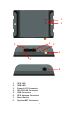
1 2 4 3 5 6 7 8 1. 2. 3. 4. 5. 6. 7. 6.
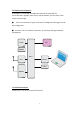
1.4 Hardware Architecture As hardware is concerned, the CAREU U1 LITE PLUS is comprised of a micro-controller, regulator, GPS receiver, 2G/3G modem, G-Force sensor, flash memory data storage. ● Users can connect PC's Hyper Terminal to the diagnostic setting port for the AVL configuration. ● G-Sensor is for car accident prevention, car tow-away warning and power management. FLASH I/O SENSOR MCU GPS RS232 Powe Modem 1.
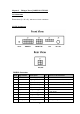
Chapter 2 Taking a Tour of CAREU U1 LITE PLUS 2.1 Dimensions Dimensions (L x W x H): 105.5mm x 72mm x 28.5mm 2.2 PIN Assignment PWR/IO Connector Pin# Signal Name Description IO Electrical Characteristic 1 DC IN Power supply input I 2 GND Signal ground G 3 Ignition Ignition(ACC) Input I DC Vin = +30 ~ +7.
Serial/CAN Connector Pin# Signal Name Description IO 1 RS232-TX RS232 Data output O 2 RS232RX RS232 Data Input I 3 Vout Supply voltage output O 4 GND Ground G 5 CAN_H CAN_H I/O 6 CAN_L CAN_L I/O IO Electrical Characteristic Vo = 5V ( Vout Total Imax = 500mA ) MIC/SPK Connector Pin# Signal Name Description 1 MIC+ Microphone Input I 2 MIC- Microphone Input I 3 SPK+ Audio output O 4 SPK- Audio output O Electrical Characteristic Chapter 3 Getting Started with C
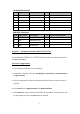
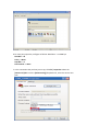
6. For Com port properties, configure as follows: Baud Rate --> 115200 bps Data Bits --> 8 Parity --> None Stop Bits --> 1 Flow Control --> None 7. In the connection that you have just set up, click File | Properties. Select the [Connect To] tab. From the [Connect using] drop down list, select the correct com port.
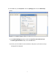
8. In the File menu, click Properties. Click the [Settings] tab. Press the ASCII Setup button. 9. In the [ASCII Sending] group box. Select both Send line ends with line feeds and Echo typed characters locally. Press the OK button. 10.Connect your the CAREU U1 LITE PLUS device and power on,The device startup message will be displayed.
. In [HyperTerminal] window, type in the command "AT$VERSION?" and press the Enter key. The hardware and firmware version will show. As long as your [HyperTerminal] window appears as the screenshot below, a connection between the device and your system has already been built up and working. It is time to send all configuration commands.
3.2 Communication Settings The CAREU U1 LITE PLUS Vehicle Tracker communicates with your control center by either SMS or 2G/3G (TCP/UDP). Before the device is installed into a vehicle, communication parameters should be set. 1. SMS Configuration Use AT$SMSDST command to set a SMS control center phone number or short code.
AT$HB=60,1 (Heartbeat setting) OK Please refer to the CAREU U1 LITE PLUS Protocol Document for more command details. 3.3 GPS Tracking Configurations After the device communication settings are done, the remote GPS tracking is ready to function. The setting of GPS tracking can be done by using AT$PDSR command. For example, AT$PDSR=1,30,0,0,2,0,0,1,0 (Tracking through GPRS by time interval 30 seconds) OK For simple testing GPRS, run the TCP Server U-Series software which is provided by S&T.
You can also apply for a testing account from S&T's FleetWeb solution through your sales contact. The main page of the Intelli FleetWeb appears as below: 3.4 Firmware Upgrade The firmware of the CAREU U1 LITE PLUS can only be updated through USB interface.
the device. Such firmware loader runs on Windows-based systems. To upgrade the firmware, follow the procedure below 1. 2. 3. 4. Connect the device to your PC with the USB cable. Connect the device to power. Power on the device. Run ServerUSeries.exe. A window displays as follows: 5. 6. 7. Press browse the button to browse to the firmware provided by S&T. Press the Start button to run the firmware program. After the writing progresses to 100%, it takes about 20 seconds for the update to completes.
GPS Antenna: Internal GPS Module: Vendor: uBlox MAX-M8Q/W Sensitivity: -167 dB ( GPS & GLONASS ) -165 dB (GPS & BeiDou ) -166 dB (GPS ) Antenna: External Time to First Fix: 1. Cold Start: 26 Seconds at open sky ( GPS & GLONASS ) 27 Seconds at open sky ( GPS & BeiDou ) 29 Seconds at open sky ( GPS ) 2. Hot Start: 1 Second 3. Aided starts: 2 Seconds at open sky ( GPS & GLONASS ) 3 Seconds at open sky (GPS & BeiDou ) 2 Seconds at open sky (GPS ) I/O(standard) Analog Input x 1 A.
Temperature Operating: –20 °C to +60 °C(With Battery) Operating: –20 °C to +70 °C(Without Battery) Storage: –20 °C to +80°C Logging TBD positions User Report TBD Sets Note: The specification herein is subject to change without prior notice. Systems & Technology Corp. (S&T), founded in 1987, is a market leader in Automatic Vehicle Locating (AVL) solutions, Geographical Information Systems (GIS) and navigation.
Chapter 5 Regulation Federal Communication Commission Interference Statement This device complies with Part 15 of the FCC Rules. Operation is subject to the following two conditions: (1) This device may not cause harmful interference, and (2) this device must accept any interference received, including interference that may cause undesired operation. This equipment has been tested and found to comply with the limits for a Class B digital device, pursuant to Part 15 of the FCC Rules.
Radiation Exposure Statement: This equipment complies with FCC radiation exposure limits set forth for an uncontrolled environment. This equipment should be installed and operated with minimum distance 20cm between the radiator & your body.