
User's Manual

4
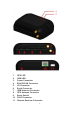
Chapter 2 Taking a Tour of CAREU U1 PLUS
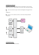
2.1 Dimensions
Dimensions (L x W x H): 72mm x 108mm x 31mm
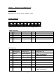
2.2 PIN Assignment
1
2 4
3
2 4
31
6
5 9
8
7
10
13
12
11
16
15
14
SERIAL PORT
I/O
POWER
4
31
6
5
2 8
7
10
921
20
19
18
17
RS-485 / CAN
24
23
22
PWR Connector
Pin#
Signal Name Description IO Electrical Characteristic
1 DC IN Power supply input I VI = DC8 to 30V,
2 GND Signal ground G
3 Ignition Ignition(ACC) Input I DC Vin = +30 ~ +7.5V (Active high)
4 Output1 Open-Collector
Output1
O Imax = 300mA
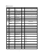
I/O Connector
Pin# Signal Name Description IO Electrical Characteristic
1 Analog Input 2 Analog input 2 I DC VIN = +30V ~ 0V
2 Input 4 Positive/ Negative I
DC VIN = +3
0V ~ +
7.5
V (High Active)
DC VIN = 0V (Low Active)
3 Input 1 Negative Trigger I
DC VIN = 0V (Low Active)
4 Input 2 Negative Trigger I
DC VIN = 0V (Low Active)
5 Analog Input 1 Analog input 1 I DC VIN = +30V ~ 0V
6 GND Signal ground G
7 Output 2 Open-Collector O Imax = 300mA
8 Output 3 Open-Collector O Imax = 300mA
9 Output 4 Open-Collector O Imax = 300mA
10 Input 3 Positive /Negative I DC VIN = +30V ~ +7.5V (High Active)
DC VIN = 0V (Low Active)