
User's Manual

Chapter 3
CAREU U1 Lite Vehicle Tracker User
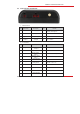
3.2 Connector Pin Assignment
Connector Pin Definition
1. PWR Connector
Pin#
Signal Name
Description
I/O
Remark
1
DC IN
Power supply input
I
DC Vin = +8 ~ +30V
Normal = 70mA @ 12V
2
GND
Signal ground
—
3
Ignition
Ignition(ACC) Input
I
DC Vin = +30 ~ +7V (Active high)
4
Output1
Open-Collector
Output1
O
Imax = 300mA
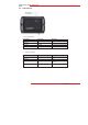
2. I/O Connector
Pin#
Signal Name
Description
I/O
Remark
1
Output 2
Open-Collector
Output 2
O
Imax = 300mA
2
GND
Signal ground
—
3
Input 2
Positive Trigger
input 2
I
DC Vin = +30 ~ +7V (Active high)
4
Input 1
Negative Trigger
input 1
I
DC VIN = +6V ~ 0V (Low Active)
5
NC
Not Connected
6
Analog Input 1
Analog input 1
I
DC VIN = +30V ~ 0V
7
NC
Not Connected
8
NC
Not Connected
9
NC
Not Connected
10
NC
Not Connected