
User's Manual

Chapter 3
12
CAREU U1 Vehicle Tracker User Guide
3.2. Connector Pin Assignment
Connector Pin Denition
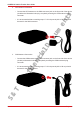
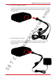
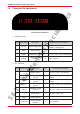
1. PWR Connector
Pin# Signal Name Description I/O Electrical Characteristic
1 DC IN Power supply input I
DC Vin = +8 ~ +30V
Normal = 70mA @ 12V
2 GND Signal ground ----
3 Ignition Ignition(ACC) Input I DC Vin = +30 ~ +0.7V (Active high)
4 Output1
Open-Collector
Output1
O Imax = 300mA
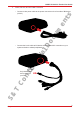
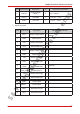
2. I/O Connector
Pin# Signal Name Description I/O Electrical Characteristic
1
Analog Input
2
Analog Input 2 I DC VIN = +30V ~ 0V (default)
Input 3
(Optional)
Positive Trigger
input 3
I
DC VIN = +30V ~ +0.7V (High
Active)
2 Input 4
Positive Trigger
input 4
I
DC VIN = +30V ~ +0.7V (High
Active)
3 Input 1
Negative Trigger
input 1
I DC VIN = +0.6V ~ 0V (Low Active)
4 Input 2
Negative Trigger
input 2
I DC VIN = +0.6V ~ 0V (Low Active)
5
Analog Input
1
Analog input 1 I DC VIN = +30V ~ 0V
6 GND Signal ground ----
7 Output 2
Open-Collector
Output 2
O Imax = 300mA
11 91 95 5 133 3 3 117 7 15
22 102 106 6 144 4 4 128 8 16
S&T Confidential Documents