
User's Manual
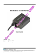

IntelliTrac A1-lite Series User Guide
Systems & Technology Corp. © 2010
This document contains confidential, restricted, and proprietary information. The document has been prepared for the
exclusive internal use of certain designated S&T employees and may not be duplicated or distributed, in whole or in
part, without the prior, written consent of an authorized officer of S&T.
- 6 -
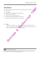
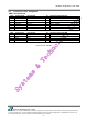
1.6 Connectors Pins Assignment
PWR / IO Connector
Pin#
Signal Name Description IO
Electrical Characteristic
1 DC IN Red I V
I
= DC8 to 30V, Inormal = 70mA @12V
2 GND Black
-
3 Ignition Brown I V
IH
min = 30V, V
IL
max = 6.8V(High Active)
4 Output1 Orange O Imax = 300mA
5 Input1 Yellow I V
IH
max = 30V, V
IL
max = 0.7V
6 Output2 Green O Imax = 300mA
SERIAL Connector
Pin#
Signal Name Description IO
Electrical Characteristic
1 Vout Blue O Vo = 5.0V, Imax = 250mA
2 TX1 Purple O
3 RX1 Gray I
4 GND White
-
Connectors pin definition