
User's Manual
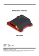

IntelliTrac A Series User Guide
Systems & Technology Corp. © 2008
This document contains confidential, restricted, and proprietary information. The document has been prepared for the
exclusive internal use of certain designated S&T employees and may not be duplicated or distributed, in whole or in
part, without the prior, written consent of an authorized officer of S&T.
- 7 -
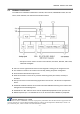
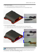
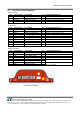
2.2 Connectors Pins Assignment
PWR Connector
Pin# Signal Name Description IO Electrical Characteristic
1 B+ Power supply input I VI = DC8V to 30V, Inormal = 70mA @ 12V
2 GND Signal ground
-
3 Ignition Ignition(ACC) Input I VIHmin = 7.0V, VILmax = 6.0V
4 Output1 Open-Collector Output1 O Imax = 300mA
I/O Connector
Pin# Signal Name Description IO Electrical Characteristic
1 Input3 Positive Trigger input3 I VIHmin = 7.0V, VILmax = 6.0V
2 Input4 Positive Trigger input4 I VIHmin = 7.0V, VILmax = 6.0V
3 Input1 Negative Trigger input1 I VIHmax = 30V, VILmax = 0.7V
4 Input2 Negative Trigger input2 I VIHmax = 30V, VILmax = 0.7V
5 Analog Input Analog input I VI = DC0V to 30V
6 GND Signal ground
-
7 Output2 Open-Collector Output2 O Imax = 300mA
8 Output3 Open-Collector Output3 O Imax = 300mA
9 CANH CAN High I VI = 2.75V to 4.5V
10 CANL CAN Low I VI = 0.5V to 2.25V
SERIAL Connector
Pin# Signal Name Description IO Electrical Characteristic
1 Vout Supply voltage output O Vo = 5.0V, Imax = 300mA
2 GND Signal ground
-
3 TX RS232 Data output O
4 RX RS232 Data input I
5 SPK+ Audio output O
6 SPK- Audio output O
V
Omax = 3.7Vpp
7 MIC+ Microphone Input I
8 MIC- Microphone Input I
RI
≈
50kΩ differential
VImax = 1.03Vpp
Connectors pin definition