
User's Manual
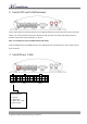
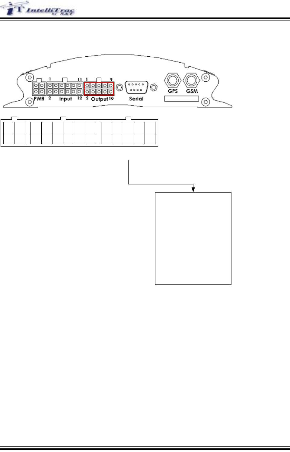
6. Install Output Cable
1
2
3
4
1
2
3
4
5
6
7
8
9
10
11
12
1
2
3
4
5
6
7
8
9
10
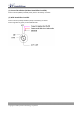
Power
Input Output
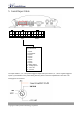
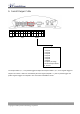
Output Connector
1 : Output1
2 : Output2
3 : Output3
4 : Output4
5 : Output5
6 : Output6
7 : Output7
8 : Output7 (via relay)
9 : External Output Power
10 : Ground
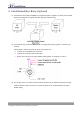
The output number 1, 2, 7 are positive triggered outputs and output number 3, 4, 5, 6 are negative triggered
outputs. Pin number 7 and 8 are controlled by the same signal (OutputID = 7), Pin7 is positive trigger and
pin8 is negative trigger. The OutputID = 8 is reserved for immobilizer control.
Copyright © 2003 Systems & Technology Corporation