uLory User Guide Version: 1.
uLory User Guide Revision History Date of Revision Document Pages Version Revised 1.0 All April 8th, 2019 Details of Revision New Copyright 2018 SystemBase Co., Ltd. All rights reserved. Website http://www.sysbas.com/ Tel +82-2-855-0501 Fax +82-2-855-0580 16F (1601) Daerung Post Tower-1, 288, Digital-ro, Guro-gu, Seoul, Republic of Korea For inquiries, please contact us at tech@sysbas.
uLory User Guide This equipment has been tested and found to comply with the limits for a Class A digital device, pursuant to part 15 of the FCC Rules. These limits are designed to provide reasonable protection against harmful interference when the equipment is operated in a commercial environment. This equipment generates, uses, and can radiate radio frequency energy and, if not installed and used in accordance with the instruction manual, may cause harmful interference to radio communications.
uLory User Guide Table of Contents 1. OVERVIEW ..................................................................................................................................... 5 2. FEATURE ......................................................................................................................................... 5 3. COMPONENTS .............................................................................................................................. 6 4. HARDWARE ......................
uLory User Guide 1. OVERVIEW ULory is a device that converts signals of RS232 Serial to LoRa to connect with Serial devices that are several kilometers away. LoRa (wireless communication technology for sensor networks), the next-generation communication of technology of Low Power Wide Area (LPWA) capable of transmitting small amounts of data over long ranges, enables communications up to 20 km in open terrain. 2.
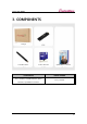
uLory User Guide 3. COMPONENTS Package 2.625dBi Antenna Product Brochure COMPONENTS uLory-1010UIL, 2.
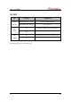
uLory User Guide 4. HARDWARE 4.1 Specification CATEGORY SUBCATEGORY SPECIFICATION Frequency Band 917 ~ 923MHz Modulation LoRa Antenna +2.625 dBi Gain Load Antenna Wired Standard USB 2.
uLory User Guide 4.2 LED LED STATUS OPERATION RDY Blink (Interval of 0.5 sec.) Operation Mode (Default) (YELLOW) Blink (Interval of 0.1 sec.) Setup Mode RXD On Reception of Data from LoRa to USB Port (RED) Off - TXD On Transmission of Data from USB Port to LoRa (GREEN) Off - * If the input voltage level is lower than the rated voltage, an operation error occurs and the RDY LED will light up at the same time.
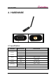
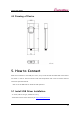
uLory User Guide 4.3 Drawing of Device 5. How to Connect After the connection to the USB port of PC, uLory will be booted and RDY LED of the device will “blink” in the 0.1-second interval under the Setup Mode and in the 0.5-second interval under the Operation Mode. * See 4.2 in the Manuals for details of LED operation. 5.1 Install USB Driver Installation - A driver, USB 2.0 A Type, needed for uLory - Download a driver from the library at http://www.sysbas.
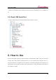
uLory User Guide - Install the downloaded driver (USB One Click Driver) after connecting uLory to USB Port of PC 5.2 Check USB Serial Port - Check if USB Serial Port is created as below after installing a driver 6. How to Use Users should adjust setting of Serial (interface, communication speed, parity bits and flow control) and LoRa (channel, Spreading Factor) for the communication between uLorys or with other devices in LoryNet via AT command or LoryView.
uLory User Guide 6.1 Switch Setting Table NUMBER STATUS DESCRIPTION ON Setup Mode OFF Operation Mode (Default) - Not used 1 2 6.2 Operation Mode Setting There are two Modes for uLory: General Communication Mode and LoryNet Mode. General Communication Mode is for the communication between PC and a device via uLory while LoryNet Mode is used for the communication in a structure of LoryNet Packet.
uLory User Guide switching Mode Switch off (Switch 1) to change it back to the Operation Mode after the completion of setup.
uLory User Guide Command Instruction Command for basic setup COMMAND DEFAULT (RANGE) DESCRIPTION AT&Z - Restart the device AT&F - AT&V - Show the current setting AT&H or ? - Show the list of commands Initialize all settings and show the initial value on the screen Shows the current AES KEY, AES IV. However, the initial AES KEY AT&E and AES IV values are not - shown. Only the changed AES KEY and AES IV values are shown.
uLory User Guide Commands for setup of LoRa COMMAND AT+PWR= DEFAULT (RANGE) DESCRIPTION Change transmission intensity of 10(1~10) LoRa 20(1~20) AT+CH= 1=917.3MHz 2=917.9MHz 3=918.5MHz 4=919.1MHz 5=919.7MHz 6=920.3MHz 7=920.7MHz 8=920.9MHz 9=921.1MHz 10=921.3MHz Change channels of LoRa 11=921.5MHz 12=921.7MHz 13=921.9MHz 14=922.1MHz 15=922.3MHz 16=922.5MHz 17=922.7MHz 18=922.9MHz 19=923.1MHz 20=923.
uLory User Guide Command for setup of Serial COMMAND DEFAULT (RANGE) DESCRIPTION N(N,O,E) AT+PAB= N=None, Set Parity Bit O=Odd, E=Even 6(0~13) AT+BAU= 0=600bps, 1=1200bps, 2=2400bps, 3=3600bps, 4=4800bps, 5=7200bps, 6=9600bps, 7=19200bps, 8=38400bps, 9=57600bps, Set baud rate 10=115200bps, 11=230400bps, 12=460800bps, 13=921600bps AT+HF= 0=OFF, 1=RTS/CTS Set flow control - Used to collect serial data and transmit it to LoRa 5(1~255) AT+DMT=<
uLory User Guide enter the value of Hex except 0x for STX - Set the length AT+STXL= in before entering the desired length; For example, in order to register number 1,2 and 3, users firstly input AT+STXL=3 and then AT+STX=31,32,33 AT+ETXL= 0(0~3) unit : byte Set the length of ETX(End of 0 = not used.
uLory User Guide follows: Length=7, STXL=3, ETXL=3, STX=31,32,33, ETX=34,35,36, Time=100. If 5671237456 is entered with less than the 1-second-interval, the number 567 will be ignored being considered as not STX because it does not satisfy the condition of Length but the second priority condition. In other words, only the number 7 will be recognized as a result of recognition of 123 for STX and 456 for ETX. Setup via utility (LoryView) The utility provided along with uLory is available on http://www.
uLory User Guide 7. Utilization LoRa is low power, mid- and long-range communication utilizing LPWA(Low Power Wide Area) communication technology. With slow speed but long range of transmission and reception, it is widely used in the area of remote monitoring and control such as smart street lighting, smart metering, smart farm, smart farming and smart factories.