sLory User Guide Version: 1.
sLory User Guide Revision History Date of Revision Document Pages Version Revised 1.0 All April 8th, 2019 Details of Revision New Copyright 2018 SystemBase Co., Ltd. All rights reserved. Website http://www.sysbas.com/ Tel +82-2-855-0501 Fax +82-2-855-0580 16F (1601) Daerung Post Tower-1, 288, Digital-ro, Guro-gu, Seoul, Republic of Korea For inquiries, please contact us at tech@sysbas.
sLory User Guide This equipment has been tested and found to comply with the limits for a Class A digital device, pursuant to part 15 of the FCC Rules. These limits are designed to provide reasonable protection against harmful interference when the equipment is operated in a commercial environment. This equipment generates, uses, and can radiate radio frequency energy and, if not installed and used in accordance with the instruction manual, may cause harmful interference to radio communications.
sLory User Guide Table of Contents 1.OVERVIEW ...................................................................................................................................... 5 2. FEATURES ....................................................................................................................................... 5 3. COMPONENTS .............................................................................................................................. 6 4. HARDWARE .......................
sLory User Guide 1. OVERVIEW sLory is a device that converts signals of RS232, RS422 and RS485 Serial to LoRa to connect with Serial devices that are several kilometers away. LoRa (wireless communication technology for sensor networks), the next-generation communication of technology of Low Power Wide Area (LPWA) capable of transmitting small amounts of data over long ranges, enables communications up to 20 km in open terrain. 2.
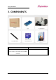
sLory User Guide 3. COMPONENTS Package 2.625dBi Antenna 5V DC Adaptor Product Brochure SystemBase Covenant COMPONENTS ORDER NUMBER sLory-1010DIL/ALL, 2.
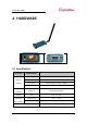
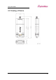
sLory User Guide 4. HARDWARE 4.1 Specification SUBCATEGORY Specification Frequency Band 917 ~ 923MHz Wireless Modulation LoRa Interface Encryption AES128 (Default setting: Disable) Antenna +2.
sLory User Guide 4.2 LED LED STATUS OPERATION RDY Blink (Interval of 0.5 sec.) Operation Mode (Default) (YELLOW) Blink (Interval of 0.1 sec.) Setup Mode SRL On (RED) Transmission and Reception of Serial Data (RS232/RS422/RS485) Off - LINK On Transmission and Reception of LoRa Data (GREEN) Off - * If the input voltage level is lower than the rated voltage, an operation error occurs and the RDY and LNK LED will light up at the same time.
sLory User Guide 4.
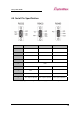
sLory User Guide 4.4 Serial Pin Specification Pin No. RS232 RS422 RS485 1 - TXD+ TRXD+ 2 RXD RXD+ - 3 TXD TXD- TRXD- 4 - - - 5 GND 6 - RXD- - 7 RTS - - 8 CTS - - 9 VCC Option (DC5V) VCC Option (DC5V) VCC Option (DC5V) * When supplying power through PIN 9, please apply DC 5V rated voltage.
sLory User Guide 5. HOW TO CONNECT No installation of programs on PC or communication device is needed for sLory. Just connect sLory to PC or Serial port of communication device and power to DC-Jack port. Then, RDY LED will blink in the interval set to 0.1 seconds under the Setup Mode and to 0.5 seconds under the Operation Mode. * See 4.2 in the manuals for the details of LED operation 6.
sLory User Guide Button Description RST Reboot the system 6.2 Operation Mode Setting There are two Modes for sLory: General Communication Mode and LoryNet Mode. General Communication Mode is for the communication between PC and a device via sLory while LoryNet Mode is used for the communication in a structure of LoryNet Packet. Setup via command Users can set AT Command via RS232 Port of a PC.
sLory User Guide Command Instruction Command for basic setup COMMAND DEFAULT (RANGE) DESCRIPTION AT&Z - AT&F - AT&V - Show the current setting AT&H or ? - Show the list of commands Restart the device Initialize all settings and show the initial value on the screen Shows the current AES KEY, AES IV. However, the initial AES KEY AT&E and AES IV values are not - shown. Only the changed AES KEY and AES IV values are shown.
sLory User Guide Commands for setup of LoRa COMMAND AT+PWR= DEFAULT (RANGE) DESCRIPTION Change transmission intensity of 10(1~10) LoRa 20(1~20) AT+CH= 1=917.3MHz 2=917.9MHz 3=918.5MHz 4=919.1MHz 5=919.7MHz 6=920.3MHz 7=920.7MHz 8=920.9MHz 9=921.1MHz 10=921.3MHz Change channels of LoRa 11=921.5MHz 12=921.7MHz 13=921.9MHz 14=922.1MHz 15=922.3MHz 16=922.5MHz 17=922.7MHz 18=922.9MHz 19=923.1MHz 20=923.
sLory User Guide Command for setup of Serial COMMAND DEFAULT (RANGE) DESCRIPTION N(N,O,E) AT+PAB= N=None, Set Parity Bit O=Odd, E=Even 6(0~13) AT+BAU= 0=600bps, 1=1200bps, 2=2400bps, 3=3600bps, 4=4800bps, 5=7200bps, 6=9600bps, 7=19200bps, 8=38400bps, 9=57600bps, Set baud rate 10=115200bps, 11=230400bps, 12=460800bps, 13=921600bps 1(1~3) AT+SER= 1=RS232 2=RS422 Set flow control 3=RS485 - Used to collect serial data and transmit it to LoRa - Wait for the
sLory User Guide - Set STX(Start of text) of Serial data - Refer to the ASCII table and enter the value of Hex except 0x for STX AT+STXL= 0(0~3) Unit: byte 0 = Not used - Set the length AT+STXL= in before entering the desired length; For example, in order to register number 1,2 and 3, users firstly input AT+STXL=3 and then AT+STX=31,32,33 - Set STX(Start of text) of Serial data - Refer to the ASCII table and enter the value of Hex except 0x for STX AT+STX= AT+STX=,
sLory User Guide AT+ETXL= before entering the desired length; For example, in order to register number 1,2 and 3, users firstly input AT+ ETXL =3 and then AT+ ETXL =31,32,33 . AT+DMS= 0(0~116) unit: byte Serial data will be transmitted to LoRa after a specific length of data as specified is received The priority is given in order of Length, STX or ETX and Time in case of that sLory includes features of Time, STX, ETX, and Length in the condition for Serial data reception.
sLory User Guide between objects, the virtual cable makes it easier to connect devices in LoryNet to establish a new and desired network by improving reception from the distant or complicated connections. Accordingly, under the LoryNet Mode, uLory reads and writes entries, which are addresses of a table to exchange data between devices with each table serving as an agency Users can refer to the LoryView Manuals for detailed instructions on LoryNet Mode.
sLory User Guide 7. Utilization LoRa is low power, mid- and long-range communication utilizing LPWA(Low Power Wide Area) communication technology. With slow speed but long range of transmission and reception, it is widely used in the area of remote monitoring and control such as smart street lighting, smart metering, smart farm, smart farming and smart factories.