sCAN User Manual Version 1.2.1 2017/09/17 www.sysbas.
Revision History Revision Date Document Version Pages Description 2015/09/04 1.0 All New 2017/08/09 1.1 6 / 4~21 Added Notes/image 2017/09/17 1.
sCAN User Manual Contents 1. sCAN .................................................................................................................... 4 1.1. About Product ................................................................................................................ 4 1.2. Composition ................................................................................................................... 4 1.3. About CANView ......................................................................
sCAN User Manual 1. sCAN 1.1. About Product This product is a convertor designed to convert the RS-232 signal to CAN and vice versa. Providing the integrated utilities at a GUI environment (communication configurations, test, firmware upgrade) Enabling power supply to DE9 (pin no.9) or CAN VBUS Providing a LED to check the communication state Supporting 1Mbps for the maximum speed of CAN communication Supporting 921.
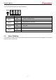
sCAN User Manual This is about the DIP-Switch back of the sCAN device. ON 1 No. Switch 1 Switch 2 Switch 3 Switch 4 1.3. 2 3 4 Status Description ON Activate a CAN VDD as power OFF Deactivate a CAN VDD as power (Default) ON Activate DE9 pin no. 9 as power OFF Deactivate DE9 pin no.
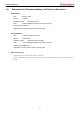
sCAN User Manual Requirements, Recommendations, and Notes on Operations 1.4.
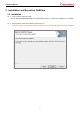
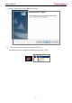
sCAN User Manual 2. Installation and Execution CANView 2.1. Installation 2.1.1. Turn on the PC and insert a CD. Move to [CD Drive]\PROGRAM folder. If the following file comes up, execute the “CANView v1.0.0.1 Setup”. 2.1.2. Press a button “Install” if the following screen pops up. If previous version of sCAN Utility is already installed, remove the old sCAN Utility prior to the installation.
sCAN User Manual 2.1.3. Press a “Finish” button once installation is completed. 2.1.4. Short-cut is installed on a desktop and program start menu). * The following figure may be different at Windows 8/Server 2012 or higher.
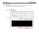
sCAN User Manual 2.2. Execution 2.2.1. Double-click the left mouth button to select a short-cut icon on the desktop to run a program. 2.2.2. The CANView screen in appeared as shown in the following figure.
sCAN User Manual 3. Program Description A program is broadly classified into 5 parts. Name Title bar Menu Toolbar Main window Status bar Description Displays the program title. Contains the basic functions of a program. Simply opens or closes the serial port. Controls sCAN based on mode. Displays device connection information and program version. The detailed description of each part is explained in the next chapter. 4. Menu Description A menu is broadly classified into 3 parts.
sCAN User Manual 4.2.1. Connect To set the serial port communication configurations and open a port. Item Baud rate Data bits Parity Stop bits Flow control 4.3. Description To set the Baudrate. Data bits is fixed at 8bit. (Other bits are unable to use since ASCII values is being used.) One of None, Even, Odd, Mark and Space can be selected/ 1bit or 2 bits can be selected. None or Hardware can be selected. Help The submenu is displayed as shown in the following figure of clicking a Help menu.
sCAN User Manual Tool Bar 5. Tool Bar Icon Description Connect Opens a serial port to connect the sCAN. Disconnect Closes a serial port. 5.1. Connect Item Baud rate Data bits Parity Stop bits Flow control Description To set the Baudrate. Data bits is fixed at 8bit. (Other bits are unable to use since ASCII values is being used.) One of None, Even, Odd, Mark and Space can be selected/ 1bit or 2 bits can be selected. None or Hardware can be selected.
sCAN User Manual 6. Main Window 6.1. Active Mode Tab The user can select if sCAN is on active mode. This windows enables receiving and sending the CAN Frame. Sender It creates and sends a CAN Frame. Auto/manual mode can be selected via an auto checkbox. Receiver A window to show the received CAN Frame. Counter The count will be increased once CAN frame is received or sent so the status of transmission can be identified.
sCAN User Manual 6.2. Setup Mode Tab The users can select if sCAN is on setup mode. This window is to set the communication configurations of sCAN. RS232 Connection Setting To set the serial communication configurations. CAN Connection Setting To set the CAN communication configurations. Option Setting To set the CAN communication options. Firmware Version To check the version of sCAN Firmware.
sCAN User Manual Apply To apply the communication configurations. Default To set the communication configurations at default. Press an “Apply” button to apply. Cancel Not to apply the communication configurations but to return to current configurations.
sCAN User Manual 6.3. Firmware Upgrade Tab The users can select if sCAN is on setup mode. This window is to firmware-upgrade the sCAN. File Path To display an absolute path of firmware file to be upgraded. Progress To display the progress of firmware upgrade. Upgrade To execute a firmware upgrade.
sCAN User Manual 7. Status Bar The status bar show the current connection. Title Message Connection displayer Connection Description To display HELP or message To display the current status of COM Port To display the current connection configurations of COM Port configurations displayer Program version 7.1. To display the current program version Connection Displayer - Connect: Connected with the sCAN device. - Disconnect: Disconnected from sCAN device. 7.2.
sCAN User Manual 8. Firmware Upgrade 8.1. The DIP-switch back of the sCAN device is to be set at setup mode. 8.2. Execute a CANView. 8.3. Click an icon, Auto Connect. 8.4. Click an Open COM port button. 8.5. Click a Firmware Upgrade tab.
sCAN User Manual 19
sCAN User Manual 8.6. Click right upper button in the file path to assign a location of HEX file. (Only English is supported for file path excluding he blank.
sCAN User Manual 8.7. Press an Upgrade button to start a firmware upgrade. 8.8. Do not disconnect the power when firmware upgrade is in process.
sCAN User Manual 9. Solution This page provides the frequently asked questions on sCAN. 9.1. CAN data is not retrievable. Check if the device is set on the active mode. You can check it via a RDY LED. Check if communication configurations are properly set. Use a DIP-witch back of the product to set the device at Setup mode. Check if both serial communication configurations and CAN communication configurations are properly set.
sCAN User Manual 10. Reference 10.1. Mask At the CAN communication, in general, it combines receiving ID and receiving mask ID to filter the CAN frame to be seen on the CAN network, thereby controlling the processing loads for communication. Receiving ID is to present the CAN frame ID to be seen, whereas the receiving Mask ID is to check all receive data are consistent the bits of the receiving ID previously set. If it’s consistent, the data is received but if not, it is not received. 10.2.
sCAN User Manual Copyright Copyright ⓒ 2020 SystemBase CO., Ltd. All rights reserved. This manual is a document protected by Copyright law. Unauthorized copying, duplicating, publishing of some or all of contents without prior consent from SystemBase is against Copyright Law. www.sysbas.
sCAN User Manual If you have any inconvenience while using the product, please contact us. Email: Working Hour • Purchase/Quotation: overseas@sysbas.com MON ~ FRI 9:00 ~ 18:00 • Technical Support/RMA: tech@sysbas.com www.sysbas.com Tel: +82-2-855-0501 Fax: +82-2-855-0580 Copyright ⓒ 2020 SystemBase Co., Ltd. All Right Reserved.