
SB4002A_Data Sheet_EN

SB4002A
9
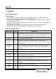
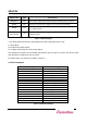
Table 2-1. PCI Bus Signals
* The above table describes the main signals used in the PCI target device only.
in: Input signal
out: Totem Pole Output signal
t/s: Tri-State. Bi-directional, tri-state in/out signal.
s/t/s: Sustained Tri-State. The low enable signal drives only one device at a time. At least one clock
must be driven to high before the Hi-Z state.
o/d: Open Drain. It is shared by numbers of devices.
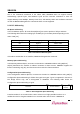
2.1.3 PCI Command
C/BE[3:0]#
Command Type
0000
Interrupt Acknowledge
0001
Special Cycle
0010
I/O Read
0011
I/O Write
0100
Reserved
0101
Reserved
0110
Memory Read
0111
Memory Write
1000
Reserved
1001
Reserved
1010
Configuration Read
1011
Configuration Write
1100
Memory Read Multiple
1101
Dual Address Cycle
1110
Memory Read Line
1111
Memory Write and Invalidate
Table 2-2. PCI Bus Command
Signal name
Type
Description
DEVSEL#
s/t/s
Device Select. Used by the selected target to indicate that it is selected.
PERR#
s/t/s
Parity Error. Indicates that a parity error occurs in the data phase.
SERR#
o/d
System Error. Indicates occurrence of a critical error such as a parity error
in the address phase.
INTA#/INTB#
INTC#/INTD#
o/d
PCI interrupt signals. These signals except INTA# are the interrupt signals
for multi functions.