
SB4002A_Data Sheet_EN


SB4002A
4
Table 3-2. WORD Data path Endian Conversion ............................................................................................ 46
Table 3-3. BYTE Data path Endian Conversion .............................................................................................. 47
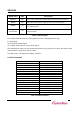
Table 4-1. Serial ROM Address Map ............................................................................................................... 49
Table 6-1. Control Register Map ...................................................................................................................... 60
Table 6-2. Base Address Space Setting Register ............................................................................................ 61
Table 6-3. Reset Register Layout .................................................................................................................... 65
Table 6-4. GPIO Out Enable Register Layout.................................................................................................. 65
Table 6-5. GPIO Output Register Layout ......................................................................................................... 66
Table 6-6. GPIO Input Register Layout ............................................................................................................ 66
Table 6-7. Interrupt Enable Register Layout .................................................................................................... 67
Table 6-8. Interrupt Polarity Register Layout ................................................................................................... 67
Table 6-9. Poll Register Layout ........................................................................................................................ 68
Table 6-10. Endian & LOCK Control Register Layout ..................................................................................... 68
Table 6-11. Muxed Pin Control Register Layout .............................................................................................. 69
Table 7-1. SB4002A Pin Description ................................................................................................................ 75
Table 7-2. Recommended Operation Conditions ............................................................................................ 77
Table 7-3. DC Characteristics .......................................................................................................................... 77
Table 8-1. PCI Bus Timing Specifications ........................................................................................................ 79
Table 8-2. Legacy Bus Timing Specifications for Write Access ....................................................................... 81
Table 8-3. Legacy Bus Timing Specifications for Read Access ....................................................................... 82