
SB4002A_Data Sheet_EN

SB4002A
22
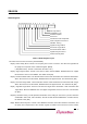
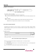
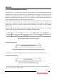
Status Register
6
Received Master Abort
Capabilities List
38 4
Reserved
10
Fast Back-to-Back Capable
014
Signaled Target Abort
9
Signaled System Error
Data Parity Error Detected
211 7 5
DEVSEL Tim ing
Detected Parity Error
12
Reserved
15 13
66 MHz Capable
Interrupt Status
Received Target Abort
Table 2-9. Status Register Layout
The status of the PCI bus of a device [downloadable]
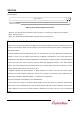
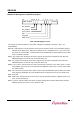
Bit[15] : Detect Parity Error. This bit is set if a parity error occurs in a device. This bit is set regardless of
the parity error response of the command register. [R/WC]
(* WC(Write Clear) : This bit is reset when the value is 1b.)
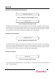
Bit[14] : Signal System Error. This bit is set when a device asserts SERR#. SB4002A does not support
this bit since it does not use SERR#. The default is 0b. [RO]
Bit[13] : Received Master Abort. The bit indicates that the master terminates the transaction with Master-
Abort. Since this bit is for the master, SB4002A does not support this bit. The default is 0b. [RO]
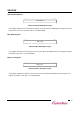
Bit[12] : Received Target Abort. The bit indicates that the master terminates the transaction with Target-
Abort. Since this bit is for the master, SB4002A does not support this bit. The default is 0b. [RO]
Bit[11] : Signaled Target Abort. This bit is set when the target device terminates a PCI transaction with
Target-Abort. Because SB4002A does not support Target-Abort, this bit is not used. The default is
0b. [RO]
Bit[10:9] : DEVSEL Timing. The bit provides information on the timing for start of the cycle and assertion
of DEVSEL#. 00b is fast, 01b is medium, and 10b is slow. Because SB4002A is a medium device,
the default is 01b. [RO]
Bit[8] : Master Data Parity Error. The bit is 1b if PERR# is asserted, the master starts the transaction, and
the parity error response bit of the common register is enabled. Since this bit is for the master,