
SB16C1058PCI_Data Sheet_EN


SB16C1058PCI
PCI Target Interface Controller
with Octal-UART
JULY 2013 REV 1.04
42
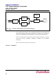
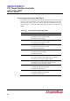
Figure 12–2: Prescaler and Baud Rate Generator Block Diagram
DLL and DLM must be written in order to program the baud rate. DLL and DLM are the
least and most significant byte of the baud rate divisor, respectively. If DLL and DLM are
both zero, the SB16C1050 is effectively disabled, as no baud clock will be generated.
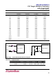
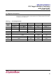
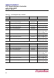
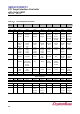
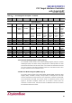
Table 12–3 shows the baud rate and divisor value for prescaler with divide by 1 as well as
crystal with frequency 1.8432MHz, 3.6864MHz, 7.3728MHz, and 14.7456MHz,
respectively.
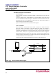
Figure 12–3 shows the crystal clock circuit reference.
Table 12–3: Baud Rates
PROGAMMABLE
CLOCK
OSCILLATOR
LOGIC
LOGIC
DIVISOR
(DIVIDE BY 4)
MCR[7] = 0
BAUD RATE
XTAL2
REFERENCE
LOGIC
INTERNAL
(DIVIDE BY 1)
LOGIC
INTERNAL
BAUD RATE
CLOCK FOR
TRANSMITTER
AND
RECEIVER
PRESCALER
XTAL1
MCR[7] = 1
PRESCALER
GENERATOR