
SB16C1058PCI_Data Sheet_EN

SB16C1058PCI
PCI Target Interface Controller
with Octal-UART
JULY 2013 REV 1.04
32
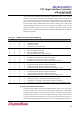
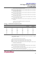
11.10 PME# Signal Resource Register (PSRR)
Select event signal to wakeup Root Complex in D3
hot
state.
Table 11–6: PME# Signal Resource Register Description
Bit
Symbol
Description
1
PSRR[1]
0b: Interrupt is not selected as Wakeup Event for waking up Root Complex (default).
1b: Interrupt is selected as Wakeup Event for waking up Root Complex.
Whether interrupt is generated or not is determined by IMR. That is, some port can only
generate interrupt or any ports among all ports can generate interrupt. When interrupt
occurs, asserts PME# signal to Root Complex.
0
PSRR[0]
0b: WAKEREQ pin is not selected as Wakeup Event for waking up Root Complex
(default).
1b: WAKEREQ pin is selected as Wakeup Event for waking up Root Complex.
When 1b is received by any logic, asserts PME# signal to Root Complex.
If PSRR[1:0] is set as 11b which means both D3
hot
-Interrupt and D3
hot
-WAKEREQ are
set, PME# signal is asserted when only one of both events occurs.
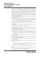
11.11 GPIO Output Enable Register (GOER)
GOER enables or disables GPIO[7:0] to output ports respectively.
Table 11–7: GPIO Output Enable Register Description
Bit
Symbol
Description
7
GOER[7]
0b: GPIO[7] is selected to input port (default).
1b: GPIO[7] is selected to output port.
6
GOER[6]
0b: GPIO[6] is selected to input port (default).
1b: GPIO[6] is selected to output port.
5
GOER[5]
0b: GPIO[5] is selected to input port (default).
1b: GPIO[5] is selected to output port.
4
GOER[4]
0b: GPIO[4] is selected to input port (default).
1b: GPIO[4] is selected to output port.
3
GOER[3]
0b: GPIO[3] is selected to input port (default).
1b: GPIO[3] is selected to output port.
2
GOER[2]
0b: GPIO[2] is selected to input port (default).
1b: GPIO[2] is selected to output port.
1
GOER[1]
0b: GPIO[1] is selected to input port (default).
1b: GPIO[1] is selected to output port.
0
GOER[0]
0b: GPIO[0] is selected to input port (default).
1b: GPIO[0] is selected to output port.