
SB16C1058PCI_Data Sheet_EN

SB16C1058PCI
PCI Target Interface Controller
with Octal-UART
JULY 2013 REV 1.04
28
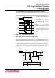
10. UART I/O Space
UART I/O Space is determined by Base Address Register 0 (10h ~ 13h) from PCI
Configuration Space. This is BAR0 area of Configuration Space and is for accessing
actual physical UARTs.
10.1 UART I/O Address Map
8 bytes per Port are assigned since the type of installed UART is 16C550 compatible
device. I/O area of BAR0 increased with number of port. For example, if it is 8 ports, I/O
area is 64 bytes (8 bytes * 8 ports) size. Space taken by first UART is the least
significant bit (LSB) and the space taken by the last UART is the most significant bit
(MSB) in continuous UART area. Number for each port is UART number + 1 and next
line shows how it is done. UART 0 = Port 1, UART 1 = Port 2, …, UART7 =PORT7.
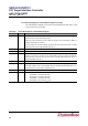
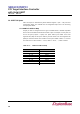
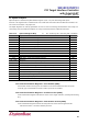
Table 10–1: UART I/O Address Map
I/O Address
8-serial Mode
00 ~ 07h
UART0
08 ~ 0Fh
UART1
10 ~ 17h
UART2
18 ~ 1Fh
UART3
20 ~ 27h
UART4
28 ~ 2Fh
UART5
30 ~ 37h
UART6
38 ~ 3Fh
UART7