
SB16C1058PCI_Data Sheet_EN

SB16C1058PCI
PCI Target Interface Controller
with Octal-UART
JULY 2013 REV 1.04
11
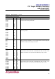
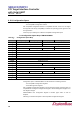
Table 6–1: Pin Description…continued
Modem and Serial I/O Interface
Name
Pin
Type
Description
DSR0#
DSR1#
DSR2#
DSR3#
DSR4#
DSR5#
DSR6#
DSR7#
44
34
22
10
176
165
142
132
I
I
I
I
I
I
I
I
Data Set Ready (active low): These pins indicate modem is powered-on and
is ready for data exchange with UART.
DCD0#
DCD1#
DCD2#
DCD3#
DCD4#
DCD5#
DCD6#
DCD7#
45
35
23
11
1
166
143
133
I
I
I
I
I
I
I
I
Carrier Detect (active low): These pins indicate that a carrier has been
detected by modem.
RI0#
RI1#
RI2#
RI3#
RI4#
RI5#
RI6#
RI7#
46
36
24
12
2
167
144
134
I
I
I
I
I
I
I
I
Ring Indicator (active low): These pins indicate the modem has received a
ringing signal from telephone line. A low to high transition on these input pins
generates a modem status interrupt, if enabled.
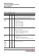
TXEN0
TXEN1
TXEN2
TXEN3
TXEN4
TXEN5
TXEN6
TXEN7
47
37
25
15
3
168
147
135
O
O
O
O
O
O
O
O
TX Enable: These pins are for auto tri-state control of the RS422 or RS485
communication. When serial date is transmitted to TXD, the value set on
ATR[5] is transmitted. These pins eliminate additional glue logic outside.
RXEN0#
RXEN1#
RXEN2#
RXEN3#
RXEN4#
RXEN5#
RXEN6#
RXEN7#
48
38
26
16
4
169
148
136
O
O
O
O
O
O
O
O
RX Enable: This pins are for auto tri-state control of the RS422 or RS485
communication. When serial date is transmitted to TXD, the value set on
ATR[7] is transmitted. These pins eliminate additional glue logic outside.