
SB16C1058PCI_Data Sheet_EN

SB16C1058PCI
PCI Target Interface Controller
with Octal-UART
JULY 2013 REV 1.04
10
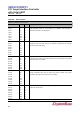
Table 6–1: Pin Description
Modem and Serial I/O Interface
Name
Pin
Type
Description
TXD0
TXD1
TXD2
TXD3
TXD4
TXD5
TXD6
TXD7
39
27
17
5
171
158
137
127
O
O
O
O
O
O
O
O
Transmit Data: These pins are individual transmit data output. During the
local loop-back mode, the TXD output pin is disabled and TXD data is
internally connected to the RXD input.
RXD0
RXD1
RXD2
RXD3
RXD4
RXD5
RXD6
RXD7
42
30
20
8
174
161
140
130
I
I
I
I
I
I
I
I
Receive Data: These pins are individual receive data input. During the local
loop-back mode, the RXD input pin is disabled and RXD data is internally
connected to the TXD output.
RTS0#
RTS1#
RTS2#
RTS3#
RTS4#
RTS5#
RTS6#
RTS7#
40
28
18
6
172
159
138
128
O
O
O
O
O
O
O
O
Request to Send (active low): These pins indicate that the UART is ready to
send data to the modem, and affect transmit and receive operations only when
Auto-RTS function is enabled.
CTS0#
CTS1#
CTS2#
CTS3#
CTS4#
CTS5#
CTS6#
CTS7#
43
33
21
9
175
162
141
131
I
I
I
I
I
I
I
I
Clear to Send (active low): These pins indicate the modem is ready to
accept transmitted data from the UART, and affect transmit and receive
operations only when Auto-CTS function is enabled.
DTR0#
DTR1#
DTR2#
DTR3#
DTR4#
DTR5#
DTR6#
DTR7#
41
29
19
7
173
160
139
129
O
O
O
O
O
O
O
O
Data Terminal Ready (active low): These pins indicate UART is ready to
transmit or receive data.