
SB16C1054PCI_Data Sheet_EN

SB16C1054PCI
PCI Target Interface Controller
with Quad-UART
JULY 2013 REV 1.04
55
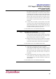
13.7 Modem Control Register (MCR, Page 0)
MCR controls the interface with the modem, data set, or peripheral device that is
emulating the modem. Table 13–7 shows MCR bit settings.
Table 13–7: Modem Control Register Description
Bit
Symbol
Description
7
MCR[7]
Clock Prescaler Select:
0b: Divide by 1 clock input (default).
1b: Divide by 4 clock input.
6
MCR[6]
Page 2 Select/Xoff Re-Transmit Access Enable:
0b: Enable access to page 0 register when LCR[7] is 0b (default).
1b: Enable access to page 2 register and Xoff re-transmit bit
when LCR[7] is 0b.
5
MCR[5]
Xon Any Enable:
0b: Disable Xon any (default).
1b: Enable Xon any.
4
MCR[4]
Internal Loop Back Enable:
0b: Disable loop back mode (default).
1b: Enable internal loop back mode. In this mode the MCR[3:0]
signals are looped back into MSR[7:4] and TXD output is
looped back to RXD input internally.
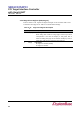
3
MCR[3]
OUT2/Interrupt Output Enable:
0b: INTx outputs disabled (default). During loop back mode,
OUT2 output 0b and it controls MSR[7] to 1b.
1b: INTx outputs enabled. During loop back mode, OUT2 output
1b and it controls MSR[7] to 0b.
OUT2 is not available as an output pin on the SB16C1050.
2
MCR[2]
OUT1/Xoff Re-transmit Enable:
0b: Xoff re-transmit disable when MCR[6] is 0b. During loop
back mode, OUT1 output to 0b and it controls MSR[6] to 1b.
1b: Xoff re-transmit enable when MCR[6] is 1b. During loop back
mode, OUT1 output to 1b and it controls MSR[6] to 0b.
OUT1 is not available as an output pin on the SB16C1050.
Xoff re-transmit is operated with XRCR, refer to XRCR.
1
MCR[1]
RTS# Output:
0b: Force RTS# output to 1b. During loop back mode, controls
MSR[4] to 1b.
1b: Force RTS# output to 0b. During loop back mode, controls
MSR[4] to 0b.
0
MCR[0]
DTR# Output:
0b: Force DTR# output to 1b. During loop back mode, controls
MSR[5] to 1b.
1b: Force DTR# output to 0b. During loop back mode, controls
MSR[5] to 0b.