
SB16C1054PCI_Data Sheet_EN

SB16C1054PCI
PCI Target Interface Controller
with Quad-UART
JULY 2013 REV 1.04
53
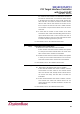
13.5 FIFO Control Register (FCR, Page 0)
FCR is used for enabling the FIFOs, clearing the FIFOs, setting transmit/receive FIFO
trigger level, and selecting the DMA modes. Table 13–5 shows FCR bit settings.
Table 13–5: FIFO Control Register Description
Bit
Symbol
Description
7:6
FCR[7:6]
RX FIFO Trigger Level Select:
00b: 8 characters (default)
01b: 16 characters
10b: 56 characters
11b: 60 characters
5:4
FCR[5:4]
TX FIFO Trigger Level Select:
00b: 8 characters (default)
01b: 16 characters
10b: 32 characters
11b: 56 characters
FCR[5:4] can only be modified and enabled when EFR[4] is set.
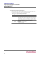
3
FCR[3]
DMA Mode Select:
0b: Set DMA mode 0 (default)
1b: Set DMA mode 1
2
FCR[2]
TX FIFO Reset:
0b: No TX FIFO reset (default)
1b: Reset TX FIFO pointers and TX FIFO level counter logic.
This bit will return to 0b after resetting FIFO.
1
FCR[1]
RX FIFO Reset:
0b: No RX FIFO reset (default)
1b: Reset RX FIFO pointers and RX FIFO level counter logic.
This bit will return to 0b after resetting FIFO.
0
FCR[0]
FIFO enable:
0b: Disable the TX and RX FIFO (default).
1b: Enable the TX and RX FIFO