
SB16C1054PCI_Data Sheet_EN


SB16C1054PCI
PCI Target Interface Controller
with Quad-UART
JULY 2013 REV 1.04
46
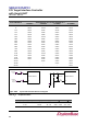
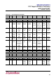
13. Register Descriptions
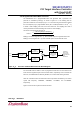
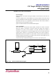
Each UART channel in the SB16C1050 has its own set of registers selected by address
lines A2, A1, and A0 with a specific channel selected. The complete register set is shown
on Table 13–1 and Table 13–2.
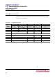
Table 13–1: Internal Registers Map
Address
A[2:0]
Page 0
Page 1
Page 2
Page 3
Page 4
LCR[7] = 0
MCR[6] = 0
LCR[7] = 1
LCR[7:0] ≠ BFh
LCR[7] = 0
MCR[6] = 1
LCR = BFh
PSR[0] = 0
LCR = BFh
PSR[0] = 1
0h
THR/RBR
DLL
—
PSR
PSR
1h
IER
DLM
—
ATR
AFR
2h
FCR/ISR
—
EFR
XRCR
3h
LCR
4h
MCR
XON1
TTR
5h
LSR
TCR
XON2
RTR
6h
MSR
RCR
XOFF1
FUR
7h
SPR
FSR
XOFF2
FLR