
SB16C1054PCI_Data Sheet_EN

SB16C1054PCI
PCI Target Interface Controller
with Quad-UART
JULY 2013 REV 1.04
37
12.2.2 Auto-CTS
Setting EFR[7] to 1b enables Auto-RTS. If enabled, data in TX FIFO are determined to be
transmitted or suspended by the value of CTS#. If 0b, it means external UART can
receive new data and data in TX FIFO are transmitted through TXD pin. If 1b, it means
external UART can not accept more data and data in TX FIFO are not transmitted. But
data being transmitted by then complete transmission. These procedures are performed
irrespective of FIFO modes. While Auto-CTS is enabled, you can verify the input value of
CTS# by FSR[1]. If 0b, CTS# is 0b and it means external UART can accept new data, If
1b, CTS# is 1b and it means external UART can not accept more data and data in TX
FIFO are not being transmitted. If IER[7] is set to 1b, interrupt is generated by Auto-CTS
when the input of CTS# is changed from 0b to 1b, and it is shown on ISR[5:0]. Interrupts
generated by Auto-CTS are removed if MSR is read.
12.3 Software Flow Control
Software flow control is performed by Xon and Xoff character transmitting/accepting.
Software flow control is enabled/disabled independently by programming EFR[3:0]
and MCR[6:5, 2]. If TX software flow control is enabled by EFR[3:2], Xoff character is
transmitted to report that data can not be accepted when the stored amount of data in
RX FIFO exceeds the value in FUR. After the CPU reads the data in RX FIFO and if
the read amount is less than the value in FLR, Xon character is transmitted to report
that more data can be accepted. If TX software flow control is enabled by EFR[1:0]
and Xoff character is inputted through RXD pin, it means no more data can be
accepted, and data transmission is suspended even though data are in TX FIFO. If
Xon character is received through RXD pin while data transmission is suspended, it
means more data can be accepted, and therefore data in TX FIFO are re-transmitted.
These procedures prevent overruns during communication. If software flow control is
disabled, overrun occurs when the transmit data rate exceeds RX FIFO service
latency. Different combinations of software flow control can be enabled by setting
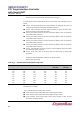
different combinations of EFR[3:0] . Table 12–1 shows software flow control options.
12.3.1 Transmit Software Flow Control
To make Transmit Software Flow Control enabled, EFR[3:2] must be set to 01b, 10b or
11b. Unlike Auto-RTS in which 0b is outputted on RTS# when TX software flow control
function is enabled, Xon character is not transmitted at first. If the amount of data in RX
FIFO (written in ISR[6] and RCR) is less than the value in FUR, Xon character is not
transmitted because Xon is in initial state. But if the amount of data in RX FIFO exceeds
the value in FUR, Xoff character is transmitted immediately. Transmitting Xoff character
means no more data can be accepted and after CPU reads data in RX FIFO, data in RX
FIFO decreases. When the amount of data in RX FIFO is same as the value of FLR, Xon
character is transmitted and it means reporting to external UART that it can accept more
data. After transmitting Xoff character, Xon character is not transmitted until the amount of