
SB16C1054PCI_Data Sheet_EN

SB16C1054PCI
PCI Target Interface Controller
with Quad-UART
JULY 2013 REV 1.04
25
9. Power Management
PCI was the most famous and useful bus since it was introduced in 1992. It is used in
various computer systems from Laptops to Servers. It supported high performance
applications by offering large bandwidth and efficiently supporting multiple masters.
Also, it offers efficient power management through Power Management and various
types of Form Factor modules and Applications.
PCI-PM defines four different Power States regarding PCI or PCI Express and interface
for controlling these Power States. This device defines two different Power States.
Refer to ‘PCI Bus Power Management Interface Specification Revision 1.2’ for more
information on Power Management.
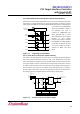
9.1 PCI Power Management
9.1.1 PCI Function Power State
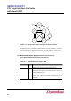
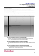
4 power states are defined for PCI function. These are D0, D1, D2 and D3; D0 is
maximum power consumption state and D3 is minimum power consumption state. D1
and D2 are middle states between D0(Power On) and D3(Power Off) and power
consumption decreases as state changes to D3. As device changes from D0 to D3, it
consumes lesser power and stores lesser Context information about current state. As a
result, waiting time needed for the device to return to D0 increases.
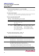
D3 Power State organizes Special Category of Power Management State and Function
can change to D3 state by physically removing Power from PCI device. D3 is classified
into two states depending on existence or absence of Vcc. Those states are D3
hot
and
D3
cold.
D3
hot
is the state where Vcc exist and it goes to maximum power-saving mode when
both power and reference clock are supplied. When software writes D0 state on
function’s PMCSR register to get out of this mode, it can change into D0 state.
D3
cold
is classified into Power Off and Sleep state depending on existence of Vaux
power.
At Power Off state, device’s main power and Vaux are cut off and execution of Wake
event is not possible. It is D3
cold
state. To get out of this state, push power button to start
system.
At Sleep state, device’s main power is cut off and only Vaux is supplied. It is D3
hot
state
and Wake event can be executed. To get out of this state, assert PME# signal to Root
Complex. The system wakeup by this can change to D0 state by re-assigning Vcc to
this device and assigning RST#.
D0 state is classified into D0
uninitialized
and D0
active
. D0
uninitialized
state is before system is
initialized after Power has been supplied and D0
active
state is after system has been
initialized.
All PCI function must support D0, D3
hot
and D3
cold.
SB16C1054PCI also support D0,
D3
hot
and D3
cold
and do not support D1 and D2.