
SB16C1054PCI_Data Sheet_EN

SB16C1054PCI
PCI Target Interface Controller
with Quad-UART
JULY 2013 REV 1.04
23
8.2 Power Management Registers of SB16C1054PCI
Sometimes control over power is needed on PCI Bus applied systems. Especially in
cases when system uses independent power source like mobile system or when PCI
device uses a lot of power, the system must limit power supply to PCI device when it is
not in use to make a power efficient system. For this reason, ‘PCI specification provides
Power Management Interface Specification’ making Power Management more
convenient. SB16C1054PCI supports PCI Power Management Interface Specification
Revision 1.2. Content of registers that are implemented at Configuration Space Header
is shown below. See ‘Power Management Spec. Rev 1.2’ for more details.
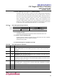
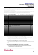
Table 8–6: Power Management Register Block
Reg40
Power management Capabilities (PMC)
Next Item Ptr
Capability ID
Reg44
Data
PMCSR_BSE Bridge
Support Extensions
Power Management
Control/Status Register (PMCSR)
8.2.1 Capability ID (40h)
Capability ID regarding Power Management Interface and default value is 01h.
8.2.2 Pointer to Next Capability (41h)
A pointer that stores address of register which has information about next Capability.
SB16C1054PCI does not have additional capabilities.
Hardwired to 0000_0000b.
8.2.3 Power Management Capabilities (42~43h)
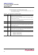
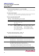
Table 8–7: Power Management Capabilities
Bit
Type
Description
15:11
RO
PME_Support: These bits indicate the power states in which the function may assert
PME#. SB16C1054PCI can assert PME# signal in D3
hot
and D3
cold
states and has value of
1_1000b.
10
RO
D2_Support: Tells if D2 Power Management State is supported. This device does not
support D2 state and the bit is set to 0b.
9
RO
D1_Support: Tells if D1 Power Management State is supported. This device does not
support D1 state and the bit is set to 0b.
8:6
RO
Aux Current: Report 3.3Vaux auxiliary current requirements for this device. This device is
configured to require 375mA which is the maximum support capacity of an electric current
supply and the bits are set to 111b.
5
RO
Device-Specific Initialization (DSI): Shows the need of DSI after transition from D3 to D0
uninitialized state. It should be set to 0b since initial value configuration for UART’s
communication is not needed here.
4
RO
Reserved
3
RO
PME Clock: Requires PCI clock to generate PME# signal and set to 0b.
2:0
RO
Version: Compatible with PCI PM Specification V1.2 and set to 011b.