
SB16C1054PCI_Data Sheet_EN

SB16C1054PCI
PCI Target Interface Controller
with Quad-UART
JULY 2013 REV 1.04
22
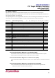
8.1.11 Base Address Registers
These are spaces for assigning Base address for accessing I/O device or memory on
PCI Local Bus. There are 6 spaces from Base Address Register 0 to 5, but spaces from
Base Address Register 2 to 5 are set as unused reserved area.
In SB16C1054PCI, Base Address Register 0 is used for UART and Base Address
Register 1 is used for Option Registers. Both of these Base Address Register spaces
are used as space for I/O. When Base Address Register Bit[0] is 0b, the space is used
as Memory space and when 1b, it is used as I/O space. Therefore, Bit[0] of Base
Address Register 0 and Base Address Register 1 are all set to value 1b.
8.1.11.1 Base Address Register0
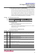
SB16C1054PCI has one Operating Mode which is Serial 4-port Mode. Base Address
Register0(BAR0) of PCI Configuration automatically sets the size of the Address Space
of four UARTs. The size of the Address Space is listed on the chart below. See ‘9.
SB16C1054PCI Register Description’ for more details.
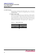
Table 8–5: I/O Address Space for four Operating Mode
Operating Mode
I/O Address Space
Serial 4-port Mode
00~1Fh
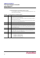
8.1.11.2 Base Address register1
Aside from UART area, SB16C1054PCI contains Option Registers area which controls
overall operations of the SB16C1054PCI. SB16C1054PCI sets this area with Base
Address Register1(BAR1. I/O Address space size of the Option I/O Register is from 00
to 1Fh. Option Registers indicate information on the two operating modes, the Line
Interface through the pin, Oscillator, Interrupt and SB16C1054PCI. See ‘9.
SB16C1054PCI Register Description’ for more details.