
SB16C1054PCI_Data Sheet_EN


SB16C1054PCI
PCI Target Interface Controller
with Quad-UART
JULY 2013 REV 1.04
20
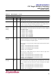
8.1.4 Status Register
Table 8–3: Status Register
Bit
Type
Description
15
RW
Detected Parity Error: This bit must be set by the device whenever it detects a parity error,
even if parity error handling is disabled. Default value of this bit is 0b.
14
RW
Signaled System Error: This bit must be set whenever the device asserts SERR#. Devices
that will never assert SERR# do not need to implement this bit.
13
RW
Received Master Abort: This bit must be set by a master device whenever its transaction is
terminated with Master-Abort. Default value of this bit is 0b.
12
RW
Received Target Abort: This bit must be set by a master device whenever its transaction is
terminated with Target-Abort. Default value of this bit is 0b.
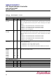
11
RW
Signaled Target Abort: This bit must be set by a target device whenever it terminates a
transaction with Target-Abort. Default value of this bit is 0b.
10:9
RO
DEVSEL Timing: These bits encode the timing of DEVSEL#. These are encoded as 00b for
fast, 01b for medium, and 10b for slow (11b is reserved). Hardwired to 01b.
8
RW
Master Data Parity Error: Set when three conditions are met: 1) the bus agent asserted
PERR# itself (on a read) or observed PERR# asserted (on a write); 2) the agent setting the
bit acted as the bus master for the operation in which the error occurred; and 3) the Parity
Error Response bit (Command register) is set. Default value of this bit is 0b.
7
RO
Fast Back-to-Back Capable: Hardwired to 0b.
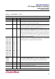
6
RO
Reserved. Hardwired to 0b.
5
RO
66MHz-Capable: Indicates whether or not this device is capable of running at 66MHz and
hardwired to 1b.
4
RO
Capabilities List: Hardwired to 1b.
3
RO
Interrupt Status: Indicates that the function has an interrupt request that has not been
processed yet. (Function is waiting to be serviced after asserting an interrupt signal. In other
words, it is 1b when INTx# signal is asserted.)
2:0
RO
Reserved. Hardwired to 000b.