
SB16C1054PCI_Data Sheet_EN


SB16C1054PCI
PCI Target Interface Controller
with Quad-UART
JULY 2013 REV 1.04
13
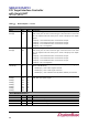
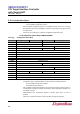
Table 6–1: Pin Description…continued
PCI Interfaces
Name
Pin
Type
Description
CLK
37
I
PCI Clock: PCI clock provides timing for all transaction on SB16C1054PCI.
RESET#
39
I
PCI Reset: Reset the SB16C1054PCI. The inputted signal indicates when the
applied main power is within the specified tolerance and stable. This signal is
asynchronous to CLK when asserted or deasserted.
INTA#
38
O/D
Interrupt A: Interrupt A is used to request an interrupt. Interrupts on PCI are
defined as “level sensitive”, asserted low, using open drain output drivers. The
assertion and deassertion of INTA# is asynchronous to CLK.
PME#
40
O/D
Power Management Event: This signal can be used by SB16C1054PCI to
request a change in the SB16C1054PCI or main system power state. The
assertion and deassertion of PME# is asynchronous to CLK. This signal has
additional electrical requirements over and above standard open drain signals
that allow it to be shared between devices that are powered off and those that
are powered on. The use of this pin is specified in the PCI Bus Power
Management Interface Specification.
AD[31], AD[30]
AD[29], AD[28]
AD[27], AD[26]
AD[25], AD[24]
AD[23], AD[22]
AD[21], AD[20]
AD[19], AD[18]
AD[17], AD[16]
AD[15], AD[14]
AD[13], AD[12]
AD[11], AD[10]
AD[09], AD[08]
AD[07], AD[06]
AD[05], AD[04]
AD[03], AD[02]
AD[01], AD[00]
41, 42
43, 44
47, 48
49, 50
53, 54
55, 56
57, 58
59, 60
76, 77
78, 79
80, 83
84, 85
87, 88
89, 90
91, 92
93, 94
T/S
T/S
T/S
T/S
T/S
T/S
T/S
T/S
T/S
T/S
T/S
T/S
T/S
T/S
T/S
T/S
Address and Data: These signals are multiplexed on the same pins. A Bus
transaction consists of an address phase followed by a data phase.
SB16C1054PCI does no support both read and write bursts.
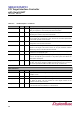
C/BE[3]#
C/BE[2]#
C/BE[1]#
C/BE[0]#
51
61
75
86
T/S
T/S
T/S
T/S
Bus Command and Byte Enables: These signals are multiplexed on same
pins. During the address phase of transaction, C/BE[3:0]# define the bus
command. During the data phase, C/BE[3:0]# are used as Byte Enables.
PAR
72
T/S
Parity: Parity is even parity across AD[31:00] and C/BE[3:0]#.
FRAME#
62
S/T/S
Cycle Frame: This signal is driven by the master of main system to indicate
the beginning and duration of an access.
IRDY#
65
S/T/S
Initiator Ready: This signal indicates the initiating agent’s(main system’s)
ability to complete the current data phase of the transaction.