
SB16C1052PCI_Data Sheet_EN

SB16C1052PCI
PCI Target Interface Controller
with Dual UART
JULY 2013 REV 1.06
54
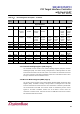
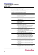
13.5 FIFO Control Register (FCR, Page 0)
FCR is used for enabling the FIFOs, clearing the FIFOs, setting transmit/receive FIFO
trigger level, and selecting the DMA modes. Table 13–5 shows FCR bit settings.
Table 13–5: FIFO Control Register Description
Bit
Symbol
Description
7:6
FCR[7:6]
RX FIFO Trigger Level Select:
00b: 8 characters (default)
01b: 16 characters
10b: 56 characters
11b: 60 characters
5:4
FCR[5:4]
TX FIFO Trigger Level Select:
00b: 8 characters (default)
01b: 16 characters
10b: 32 characters
11b: 56 characters
FCR[5:4] can only be modified and enabled when EFR[4] is set.
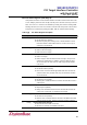
3
FCR[3]
DMA Mode Select:
0b: Set DMA mode 0 (default)
1b: Set DMA mode 1
2
FCR[2]
TX FIFO Reset:
0b: No TX FIFO reset (default)
1b: Reset TX FIFO pointers and TX FIFO level counter logic.
This bit will return to 0b after resetting FIFO.
1
FCR[1]
RX FIFO Reset:
0b: No RX FIFO reset (default)
1b: Reset RX FIFO pointers and RX FIFO level counter logic.
This bit will return to 0b after resetting FIFO.
0
FCR[0]
FIFO enable:
0b: Disable the TX and RX FIFO (default).
1b: Enable the TX and RX FIFO