
SB16C1052PCI_Data Sheet_EN

SB16C1052PCI
PCI Target Interface Controller
with Dual UART
JULY 2013 REV 1.06
46
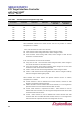
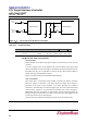
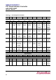
Figure 12–3: Crystal Clock Circuit Reference Diagram
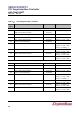
Table 12–4: Component Values
Frequency Range (MHz)
C1 (pF)
C2 (pF)
R1 (Ω)
R2(Ω)
3.6~8
22
68
220K
470 ~ 1.5K
8~16
33~68
33 ~ 68
220K ~ 2.2M
470 ~ 1.5K
12.6 Break and Time-out Conditions
Break Condition:
Break Condition occurs when TXD signal outputs 0b and sustains for more than one
character.
It occurs if LCR[6] is set to 1b and deleted if 0b. If break condition occurs when normal
data are transmitted on TXD, break signal is transmitted and internal serial data are also
transmitted, but they are not outputted to external TXD pin. When Break condition is
deleted, then they are transmitted to TXD pin.
Figure 12–4 below shows the Break Condition Block Diagram.
Time-out Condition:
When serial data is received from external UART, characters are stored in RX FIFO.
When the number of characters in RX FIFO reaches the trigger level, interrupt is
generated for the CPU to treat characters in RX FIFO. But when the number of
characters in RX FIFO does not reach the trigger level and no more data arrives from
external device, interrupt is not generated and therefore CPU cannot recognize it.
SB16C1050 offers time-out function for this situation. Time-out function generates an
interrupt and reports to CPU when the number of RX FIFO is less than trigger level and
no more data receives for four character time.
Time-out interrupt is enabled when IER[2] is set to 1b and can be verified by ISR.
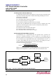
SB16C1052PCI
XIN
XOUT
XIN
Clock
Clock XOUT
Output
SB16C1052PCI
C2
Optional
External
C1
R1 CRYSTAL
R2