
SB16C1052PCI_Data Sheet_EN


SB16C1052PCI
PCI Target Interface Controller
with Dual UART
JULY 2013 REV 1.06
40
12.3.1 Transmit Software Flow Control
To make Transmit Software Flow Control enabled, EFR[3:2] must be set to 01b, 10b or
11b. Unlike Auto-RTS in which 0b is outputted on RTS# when TX software flow control
function is enabled, Xon character is not transmitted at first. If the amount of data in RX
FIFO (written in ISR[6] and RCR) is less than the value in FUR, Xon character is not
transmitted because Xon is in initial state. But if the amount of data in RX FIFO exceeds
the value in FUR, Xoff character is transmitted immediately. Transmitting Xoff character
means no more data can be accepted and after CPU reads data in RX FIFO, data in RX
FIFO decreases. When the amount of data in RX FIFO is same as the value of FLR, Xon
character is transmitted and it means reporting to external UART that it can accept more
data. After transmitting Xoff character, Xon character is not transmitted until the amount of
data in RX FIFO is same as the value of FLR.
The value of FLR is determined by FIFO mode. If FCR[7:6] is 00b, 01, 10 , and 11b,
FUR is 8, 16, 56, and 60, respectively. And if FCR[5:4] is 00b, 01b, 10b, and 11b, FLR is
0, 8, 16, and 56, respectively in 64-byte FIFO. In 256-byte FIFO mode, users can input
values in FUR and FLR as they want and use them. But the value in FUR must be larger
than that of FLR. While TX software flow control is active, its status (if Xon or Xoff) can be
verified by FSR[4]. If FSR[4] is 0b, the status is Xon and if 1b, the status is Xoff. It can be
verified by FSR[4] only. And for there is no condition to generate interrupt, interrupt
doesn’t occur. It is different from that interrupt is generated by IER[5] when RX software
flow control is enabled.
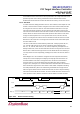
12.3.2 Receive Software Flow Control
To make Receive Software Flow Control enabled, EFR[1:0] must be set to 01b, 10b or
11b. When enabled, data in TX FIFO are determined to be transmitted or suspended by
incoming Xon/Xoff characters. If Xon character is received, it means external UART can
accept new data, and data in TX FIFO are transmitted through TXD pin. If Xoff character
is received, it means external UART can not accept more data, and data in TX FIFO are
not transmitted. But data being transmitted by that time are completely transmitted. These
procedures are performed irrespective of FIFO modes. While Receive Software Flow
Control is enabled, you can verify if the RX Software Flow Control status is XON or XOFF
by FSR[0]. If it is 0b, RX Software Flow Control status is XON and it means external
UART can accept new data. If 1b, RX Software Flow Control status is XOFF and it means
external UART can not accept more data and data in TX FIFO are not being transmitted.
If IER[5] is set to 1b, interrupt is generated when Xoff character is received and it is
shown on ISR[5:0]. Interrupts generated by RX Software Flow Control are removed if ISR
is read or Xon character is received.
General problems in using XON/XOFF function and tips for using Xon/Xoff character as
one character are as follows.
■
■
When RX Software Flow Control and Auto-CTS are enabled, LSR’s Transmit Empty
Bit and Transmit Holding Empty Bit are not affected even though RX Flow Control
status is XOFF or 1b is inputted on CTS# pin, so data in TX FIFO are suspended.
That is, these two bits are set to 1b if there is space available in TX FIFO.
Xon/Xoff character which generated parity error are treated as normal Xon/Xoff