
SB16C1052PCI_Data Sheet_EN

SB16C1052PCI
PCI Target Interface Controller
with Dual UART
JULY 2013 REV 1.06
34
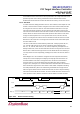
11.10 GPIO Output Enable Register (GOER)
GOER enables or disables GPIO[7:0] to output ports respectively.
Table 11–9: GPIO Output Enable Register Description
Bit
Symbol
Description
7
GOER[7]
0b: GPIO[7] is selected to input port (default).
1b: GPIO[7] is selected to output port.
6
GOER[6]
0b: GPIO[6] is selected to input port (default).
1b: GPIO[6] is selected to output port.
5
GOER[5]
0b: GPIO[5] is selected to input port (default).
1b: GPIO[5] is selected to output port.
4
GOER[4]
0b: GPIO[4] is selected to input port (default).
1b: GPIO[4] is selected to output port.
3
GOER[3]
0b: GPIO[3] is selected to input port (default).
1b: GPIO[3] is selected to output port.
2
GOER[2]
0b: GPIO[2] is selected to input port (default).
1b: GPIO[2] is selected to output port.
1
GOER[1]
0b: GPIO[1] is selected to input port (default).
1b: GPIO[1] is selected to output port.
0
GOER[0]
0b: GPIO[0] is selected to input port (default).
1b: GPIO[0] is selected to output port.
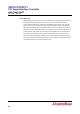
11.11 GPIO Output Register (GOR)
GOR sets output of GPIO[7:0] respectively.
Table 11–10: GPIO Output Register Description
Bit
Symbol
Description
7
GOR[7]
Sets the output of GPIO[7].
6
GOR[6]
Sets the output of GPIO[6].
5
GOR[5]
Sets the output of GPIO[5].
4
GOR[4]
Sets the output of GPIO[4].
3
GOR[3]
Sets the output of GPIO[3].
2
GOR[2]
Sets the output of GPIO[2].
1
GOR[1]
Sets the output of GPIO[1].
0
GOR[0]
Sets the output of GPIO[0].