
IOM SYSLOOP (IOM SL 01 S 3GB)
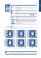
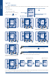
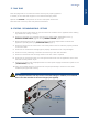
Table Of Contents
- CONTENTS
- 1. GENERAL RECOMMENDATIONS
- 2. INSPECTION AND STORAGE
- 3. WARRANTY
- 4. CONTENTS Of PACKAGE
- 5. DIMENSIONS
- 6. HANDLING
- 7. REFRIGERATION SPECIFICATIONS
- 8. TECHNICAL SPECIFICATIONS
- 9. ELECTRIC SPECIFICATIONS
- 10. INSTALLATION
- 11. DUCTING AND NOISE LEVEL REDUCTION
- 12. UNCLAMPING THE COMPRESSOR
- 13. HYDRAULIC LINKS
- 14. WIRING DIAGRAM AND LEGEND
- 15. ELECTRICAL CONNECTIONS
- 16. REGULATION
- 17. FINAL TASKS
- 18. STARTING - RECOMMENDATIONS - SETTINGS
- 19. MAINTENANCE AND SERVICING
- 19.1. FAULT FINDING
- 19.1.1. NEITHER THE FAN NOR THE COMPRESSOR OPERATE
- 19.1.2. VENTILATION (FAN) MODE OPERATES BUT THE COMPRESSOR DOES NOT OPERATE
- 19.1.3. INSUFFICIENT COOLING OR HEATING PRODUCTION
- 19.1.4. INSUFFICIENT WATER FLOW AT THE LEVEL OF THE COAXIAL EXCHANGER.
- 19.1.5. APPEARANCE OF WATER DROPLETS IN THE APPLIANCE
- 19.1.6. APPEARANCE OF ABNORMAL NOISES AND VIBRATIONS IN THE CASING
- 19.2. ALARM CODES
- 19.1. FAULT FINDING
- 20. IN CASE OF WARRANTY - MATERIAL RETURN PROCEDURE
- 21. ORDERING SERVICE AND SPARE PARTS ORDER
- DIMENSIONS
- CONFIGURATION R1.AI RECT/S4.AO RECT
- CONFIGURATION R2.AI RECT/S4.AO RECT
- CONFIGURATION R1.AI 1Ø200/S4.AO RECT OR R1.AI 1Ø200 FAØ100/S4.AO RECT OR R1.AI 1Ø200 FAØ125/S4.AO RECT
- CONFIGURATION R2.AI 1Ø200/S4.AO RECT OR R2.AI 1Ø200 FAØ100/S4.AO RECT OR R2.AI 1Ø200 FAØ125/S4.AO RECT
- CONFIGURATION R1.AI RECT/S4.AO 1Ø200 OR R1.AI RECT/S3.AO 1Ø200
- CONFIGURATION R2.AI RECT/S4.AO 1Ø200 OR R2.AI RECT/S3.AO 1Ø200
- CONFIGURATION R1.AI 1Ø200/S4.AO 1Ø200 OR R1.AI 1Ø200 FAØ100/S4.AO 1Ø200 OR R1.AI 1Ø200 FAØ125/S4.AO 1Ø200 OR R1.AI 1Ø200/S3.AO 1Ø200 OR R1.AI 1Ø200 FAØ100/S3.AO 1Ø200 OR R1.AI 1Ø200 FAØ125/S3.AO 1Ø200
- CONFIGURATION R2.AI 1Ø200/S4.AO 1Ø200 OR R2.AI 1Ø200 FAØ100/S4.AO 1Ø200 OR R2.AI 1Ø200 FAØ125/S4.AO 1Ø200 OR R2.AI 1Ø200/S3.AO 1Ø200 OR R2.AI 1Ø200 FAØ100/S3.AO 1Ø200 OR R2.AI 1Ø200 FAØ125/S3.AO 1Ø200
- CONFIGURATION AO XLN
- WIRING DIAGRAM
- DIMENSIONS
- CONFIGURATION R1.AI RECT/S4.AO RECT
- CONFIGURATION R2.AI RECT/S4.AO RECT
- CONFIGURATION R1.AI 1Ø200/S4.AO RECT OU R1.AI 1Ø200 FAØ100/S4.AO RECT OU R1.AI 1Ø200 FAØ125/S4.AO RECT
- CONFIGURATION R2.AI 1Ø200/S4.AO RECT OU R2.AI 1Ø200 FAØ100/S4.AO RECT OU R2.AI 1Ø200 FAØ125/S4.AO RECT
- CONFIGURATION R1.AI RECT/S4.AO 1Ø200 OU R1.AI RECT/S3.AO 1Ø200
- CONFIGURATION R2.AI RECT/S4.AO 1Ø200 OU R2.AI RECT/S3.AO 1Ø200
- CONFIGURATION R1.AI 1Ø200/S4.AO 1Ø200 OU R1.AI 1Ø200 FAØ100/S4.AO 1Ø200 OU R1.AI 1Ø200 FAØ125/S4.AO 1Ø200 OU R1.AI 1Ø200/S3.AO 1Ø200 OU R1.AI 1Ø200 FAØ100/S3.AO 1Ø200 OU R1.AI 1Ø200 FAØ125/S3.AO 1Ø200
- CONFIGURATION R2.AI 1Ø200/S4.AO 1Ø200 OU R2.AI 1Ø200 FAØ100/S4.AO 1Ø200 OU R2.AI 1Ø200 FAØ125/S4.AO 1Ø200 OU R2.AI 1Ø200/S3.AO 1Ø200 OU R2.AI 1Ø200 FAØ100/S3.AO 1Ø200 OU R2.AI 1Ø200 FAØ125/S3.AO 1Ø200
- CONFIGURATION AO XLN
- SCHEMAS ELECTRIQUES
- ABMESSUNGEN
- KONFIGURATION R1.AI RECT/S4.AO RECT
- KONFIGURATION R2.AI RECT/S4.AO RECT
- KONFIGURATION R1.AI 1Ø200/S4.AO RECT ODER R1.AI 1Ø200 FAØ100/S4.AO RECT ODER R1.AI 1Ø200 FAØ125/S4.AO RECT
- KONFIGURATION R2.AI 1Ø200/S4.AO RECT ODER R2.AI 1Ø200 FAØ100/S4.AO RECT ODER R2.AI 1Ø200 FAØ125/S4.AO RECT
- KONFIGURATION R1.AI RECT/S4.AO 1Ø200 ODER R1.AI RECT/S3.AO 1Ø200
- KONFIGURATION R2.AI RECT/S4.AO 1Ø200 ODER R2.AI RECT/S3.AO 1Ø200
- KONFIGURATION R1.AI 1Ø200/S4.AO 1Ø200 ODER R1.AI 1Ø200 FAØ100/S4.AO 1Ø200 ODER R1.AI 1Ø200 FAØ125/S4.AO 1Ø200 ODER R1.AI 1Ø200/S3.AO 1Ø200 ODER R1.AI 1Ø200 FAØ100/S3.AO 1Ø200 ODER R1.AI 1Ø200 FAØ125/S3.AO 1Ø200
- KONFIGURATION R2.AI 1Ø200/S4.AO 1Ø200 ODER R2.AI 1Ø200 FAØ100/S4.AO 1Ø200 ODER R2.AI 1Ø200 FAØ125/S4.AO 1Ø200 ODER R2.AI 1Ø200/S3.AO 1Ø200 ODER R2.AI 1Ø200 FAØ100/S3.AO 1Ø200 ODER R2.AI 1Ø200 FAØ125/S3.AO 1Ø200
- KONFIGURATION AO XLN
- STROMLAUFPLANS
- DIMENSIONI
- CONFIGURAZIONE R1.AI RECT/S4.AO RECT
- CONFIGURAZIONE R2.AI RECT/S4.AO RECT
- CONFIGURAZIONE R1.AI 1Ø200/S4.AO RECT O R1.AI 1Ø200 FAØ100/S4.AO RECT O R1.AI 1Ø200 FAØ125/S4.AO RECT
- CONFIGURAZIONE R2.AI 1Ø200/S4.AO RECT O R2.AI 1Ø200 FAØ100/S4.AO RECT O R2.AI 1Ø200 FAØ125/S4.AO RECT
- CONFIGURAZIONE R1.AI RECT/S4.AO 1Ø200 O R1.AI RECT/S3.AO 1Ø200
- CONFIGURAZIONE R2.AI RECT/S4.AO 1Ø200 O R2.AI RECT/S3.AO 1Ø200
- CONFIGURAZIONE R1.AI 1Ø200/S4.AO 1Ø200 O R1.AI 1Ø200 FAØ100/S4.AO 1Ø200 O R1.AI 1Ø200 FAØ125/S4.AO 1Ø200 O R1.AI 1Ø200/S3.AO 1Ø200 O R1.AI 1Ø200 FAØ100/S3.AO 1Ø200 O R1.AI 1Ø200 FAØ125/S3.AO 1Ø200
- CONFIGURAZIONE R2.AI 1Ø200/S4.AO 1Ø200 O R2.AI 1Ø200 FAØ100/S4.AO 1Ø200 O R2.AI 1Ø200 FAØ125/S4.AO 1Ø200 O R2.AI 1Ø200/S3.AO 1Ø200 O R2.AI 1Ø200 FAØ100/S3.AO 1Ø200 O R2.AI 1Ø200 FAØ125/S3.AO 1Ø200
- CONFIGURAZIONE AO XLN
- SCHEMA ELETRICO
- DIMENSIONES
- CONFIGURACIÓN R1.AI RECT/S4.AO RECT
- CONFIGURACIÓN R2.AI RECT/S4.AO RECT
- CONFIGURACIÓN R1.AI 1Ø200/S4.AO RECT O R1.AI 1Ø200 FAØ100/S4.AO RECT O R1.AI 1Ø200 FAØ125/S4.AO RECT
- CONFIGURACIÓN R2.AI 1Ø200/S4.AO RECT O R2.AI 1Ø200 FAØ100/S4.AO RECT O R2.AI 1Ø200 FAØ125/S4.AO RECT
- CONFIGURACIÓN R1.AI RECT/S4.AO 1Ø200 O R1.AI RECT/S3.AO 1Ø200
- CONFIGURACIÓN R2.AI RECT/S4.AO 1Ø200 O R2.AI RECT/S3.AO 1Ø200
- CONFIGURACIÓN R1.AI 1Ø200/S4.AO 1Ø200 O R1.AI 1Ø200 FAØ100/S4.AO 1Ø200 O R1.AI 1Ø200 FAØ125/S4.AO 1Ø200 O R1.AI 1Ø200/S3.AO 1Ø200 O R1.AI 1Ø200 FAØ100/S3.AO 1Ø200 O R1.AI 1Ø200 FAØ125/S3.AO 1Ø200
- CONFIGURACIÓN R2.AI 1Ø200/S4.AO 1Ø200 O R2.AI 1Ø200 FAØ100/S4.AO 1Ø200 O R2.AI 1Ø200 FAØ125/S4.AO 1Ø200 O R2.AI 1Ø200/S3.AO 1Ø200 O R2.AI 1Ø200 FAØ100/S3.AO 1Ø200 O R2.AI 1Ø200 FAØ125/S3.AO 1Ø200
- CONFIGURACIÓN AO XLN
- ESQUEMA ELECTRICO

English
26 SYSLOOP
1. With the key on the control modules, select HEAT mode and then set the maximum
temperature with the UP and DOWN arrows. The ambient temperature should be within the
operating limits (Refer to the § OPERATING LIMITS, page 7). In the same way, during the pre-
commissioning checks the exchanger pump(s) water loop inlet temperature should be within the
limits corresponding to each operating mode (Refer to the § OPERATING LIMITS, page 7).
Reminder: if one of these factors is situated at its minimum or maximum level, the other should be
situated at a normal level in order to ensure the unit’s correct and normal operation.
2. Ensure that the thermostat is connected properly and set the set temperature above the ambient
temperature of the zone to be cooled. After 3 minutes, the compressor starts operating.
3. When the appliance has been operating for a few minutes, check the presence of hot air at the
blowing grille.
4. When the appliance has been operating for a few minutes, check the temperature of the unit’s outlet
water. Generally, this should be around 3°C below the unit’s water loop inlet temperature. A variance
lower than 2°C indicates that the water ow is too high, whilst a variance higher than 6°C indicates
that the water ow is too low.
5. Adjust the isolation/balancing valve on the outlet water pipe to obtain the appliance’s nominal water
ow (Refer to the Maker’s Plate)
6. Check for the absence of vibrations and water leaks.
7. When all the above tests have been completed, adjust the system to maintain the desired comfort
level.
After performing all the above-mentioned checks, proceed with creating a demand for Cooling and Heating
or vice versa.
18.1. COMMISSIONING
18.1.1. DEMAND FOR COOLING
1. With the key on the control module, select COOL mode and then set the minimum
temperature with the UP and DOWN arrows. The ambient temperature should be within the
operating limits (Refer to the § OPERATING LIMITS, page 7). In the same way, during the pre-
commissioning checks, the exchanger pump(s) water loop inlet temperature should be within the
limits corresponding to each operating mode (Refer to the § OPERATING LIMITS, page 7).
Reminder: if one of these factors is situated at its minimum or maximum level, the other should be
situated at a normal level in order to ensure the unit’s correct and normal operation.
2. Ensure that the thermostat is connected properly and set the set temperature below the ambient
temperature of the zone to be cooled. After 3 minutes, the compressor starts operating.
3. When the appliance has been operating for a few minutes, check the presence of cold air at the
blowing grille.
4. When the appliance has been operating for a few minutes, check the temperature of the unit’s outlet
water. Generally, this should be around 5°C above the unit’s water loop inlet temperature. A variance
lower than 3.5°C indicates that the water ow is too high, whilst a variance higher than 8°C indicates
that the water ow is too low.
5. Adjust the isolation/balancing valve on the outlet water pipe to obtain the appliance’s nominal water
ow (Refer to the Maker’s Plate)
6. Check that the condensates drainage system is working properly and check that a siphon is included
in the drainage line.
7. Check for the absence of vibrations and water leaks.
8. When all the above tests have been completed, adjust the system to maintain the desired comfort
level.
18.1.2. DEMAND FOR HEATING
Note: If the unit does not operate, perform a fault diagnosis (Refer to the § MAINTENANCE AND SERVICING,
page 27). If the fault analysis does not enable the cause of the problem(s) to be determined or if the unit
still does not operate, contact a qualied after-sales technician to obtain a correct diagnosis and to repair
the equipment.