
IOM SYSLOOP (IOM SL 01 S 3GB)
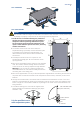
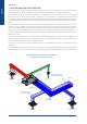
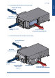
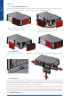
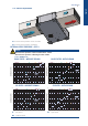
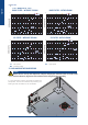
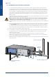
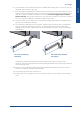
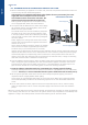
Table Of Contents
- CONTENTS
- 1. GENERAL RECOMMENDATIONS
- 2. INSPECTION AND STORAGE
- 3. WARRANTY
- 4. CONTENTS Of PACKAGE
- 5. DIMENSIONS
- 6. HANDLING
- 7. REFRIGERATION SPECIFICATIONS
- 8. TECHNICAL SPECIFICATIONS
- 9. ELECTRIC SPECIFICATIONS
- 10. INSTALLATION
- 11. DUCTING AND NOISE LEVEL REDUCTION
- 12. UNCLAMPING THE COMPRESSOR
- 13. HYDRAULIC LINKS
- 14. WIRING DIAGRAM AND LEGEND
- 15. ELECTRICAL CONNECTIONS
- 16. REGULATION
- 17. FINAL TASKS
- 18. STARTING - RECOMMENDATIONS - SETTINGS
- 19. MAINTENANCE AND SERVICING
- 19.1. FAULT FINDING
- 19.1.1. NEITHER THE FAN NOR THE COMPRESSOR OPERATE
- 19.1.2. VENTILATION (FAN) MODE OPERATES BUT THE COMPRESSOR DOES NOT OPERATE
- 19.1.3. INSUFFICIENT COOLING OR HEATING PRODUCTION
- 19.1.4. INSUFFICIENT WATER FLOW AT THE LEVEL OF THE COAXIAL EXCHANGER.
- 19.1.5. APPEARANCE OF WATER DROPLETS IN THE APPLIANCE
- 19.1.6. APPEARANCE OF ABNORMAL NOISES AND VIBRATIONS IN THE CASING
- 19.2. ALARM CODES
- 19.1. FAULT FINDING
- 20. IN CASE OF WARRANTY - MATERIAL RETURN PROCEDURE
- 21. ORDERING SERVICE AND SPARE PARTS ORDER
- DIMENSIONS
- CONFIGURATION R1.AI RECT/S4.AO RECT
- CONFIGURATION R2.AI RECT/S4.AO RECT
- CONFIGURATION R1.AI 1Ø200/S4.AO RECT OR R1.AI 1Ø200 FAØ100/S4.AO RECT OR R1.AI 1Ø200 FAØ125/S4.AO RECT
- CONFIGURATION R2.AI 1Ø200/S4.AO RECT OR R2.AI 1Ø200 FAØ100/S4.AO RECT OR R2.AI 1Ø200 FAØ125/S4.AO RECT
- CONFIGURATION R1.AI RECT/S4.AO 1Ø200 OR R1.AI RECT/S3.AO 1Ø200
- CONFIGURATION R2.AI RECT/S4.AO 1Ø200 OR R2.AI RECT/S3.AO 1Ø200
- CONFIGURATION R1.AI 1Ø200/S4.AO 1Ø200 OR R1.AI 1Ø200 FAØ100/S4.AO 1Ø200 OR R1.AI 1Ø200 FAØ125/S4.AO 1Ø200 OR R1.AI 1Ø200/S3.AO 1Ø200 OR R1.AI 1Ø200 FAØ100/S3.AO 1Ø200 OR R1.AI 1Ø200 FAØ125/S3.AO 1Ø200
- CONFIGURATION R2.AI 1Ø200/S4.AO 1Ø200 OR R2.AI 1Ø200 FAØ100/S4.AO 1Ø200 OR R2.AI 1Ø200 FAØ125/S4.AO 1Ø200 OR R2.AI 1Ø200/S3.AO 1Ø200 OR R2.AI 1Ø200 FAØ100/S3.AO 1Ø200 OR R2.AI 1Ø200 FAØ125/S3.AO 1Ø200
- CONFIGURATION AO XLN
- WIRING DIAGRAM
- DIMENSIONS
- CONFIGURATION R1.AI RECT/S4.AO RECT
- CONFIGURATION R2.AI RECT/S4.AO RECT
- CONFIGURATION R1.AI 1Ø200/S4.AO RECT OU R1.AI 1Ø200 FAØ100/S4.AO RECT OU R1.AI 1Ø200 FAØ125/S4.AO RECT
- CONFIGURATION R2.AI 1Ø200/S4.AO RECT OU R2.AI 1Ø200 FAØ100/S4.AO RECT OU R2.AI 1Ø200 FAØ125/S4.AO RECT
- CONFIGURATION R1.AI RECT/S4.AO 1Ø200 OU R1.AI RECT/S3.AO 1Ø200
- CONFIGURATION R2.AI RECT/S4.AO 1Ø200 OU R2.AI RECT/S3.AO 1Ø200
- CONFIGURATION R1.AI 1Ø200/S4.AO 1Ø200 OU R1.AI 1Ø200 FAØ100/S4.AO 1Ø200 OU R1.AI 1Ø200 FAØ125/S4.AO 1Ø200 OU R1.AI 1Ø200/S3.AO 1Ø200 OU R1.AI 1Ø200 FAØ100/S3.AO 1Ø200 OU R1.AI 1Ø200 FAØ125/S3.AO 1Ø200
- CONFIGURATION R2.AI 1Ø200/S4.AO 1Ø200 OU R2.AI 1Ø200 FAØ100/S4.AO 1Ø200 OU R2.AI 1Ø200 FAØ125/S4.AO 1Ø200 OU R2.AI 1Ø200/S3.AO 1Ø200 OU R2.AI 1Ø200 FAØ100/S3.AO 1Ø200 OU R2.AI 1Ø200 FAØ125/S3.AO 1Ø200
- CONFIGURATION AO XLN
- SCHEMAS ELECTRIQUES
- ABMESSUNGEN
- KONFIGURATION R1.AI RECT/S4.AO RECT
- KONFIGURATION R2.AI RECT/S4.AO RECT
- KONFIGURATION R1.AI 1Ø200/S4.AO RECT ODER R1.AI 1Ø200 FAØ100/S4.AO RECT ODER R1.AI 1Ø200 FAØ125/S4.AO RECT
- KONFIGURATION R2.AI 1Ø200/S4.AO RECT ODER R2.AI 1Ø200 FAØ100/S4.AO RECT ODER R2.AI 1Ø200 FAØ125/S4.AO RECT
- KONFIGURATION R1.AI RECT/S4.AO 1Ø200 ODER R1.AI RECT/S3.AO 1Ø200
- KONFIGURATION R2.AI RECT/S4.AO 1Ø200 ODER R2.AI RECT/S3.AO 1Ø200
- KONFIGURATION R1.AI 1Ø200/S4.AO 1Ø200 ODER R1.AI 1Ø200 FAØ100/S4.AO 1Ø200 ODER R1.AI 1Ø200 FAØ125/S4.AO 1Ø200 ODER R1.AI 1Ø200/S3.AO 1Ø200 ODER R1.AI 1Ø200 FAØ100/S3.AO 1Ø200 ODER R1.AI 1Ø200 FAØ125/S3.AO 1Ø200
- KONFIGURATION R2.AI 1Ø200/S4.AO 1Ø200 ODER R2.AI 1Ø200 FAØ100/S4.AO 1Ø200 ODER R2.AI 1Ø200 FAØ125/S4.AO 1Ø200 ODER R2.AI 1Ø200/S3.AO 1Ø200 ODER R2.AI 1Ø200 FAØ100/S3.AO 1Ø200 ODER R2.AI 1Ø200 FAØ125/S3.AO 1Ø200
- KONFIGURATION AO XLN
- STROMLAUFPLANS
- DIMENSIONI
- CONFIGURAZIONE R1.AI RECT/S4.AO RECT
- CONFIGURAZIONE R2.AI RECT/S4.AO RECT
- CONFIGURAZIONE R1.AI 1Ø200/S4.AO RECT O R1.AI 1Ø200 FAØ100/S4.AO RECT O R1.AI 1Ø200 FAØ125/S4.AO RECT
- CONFIGURAZIONE R2.AI 1Ø200/S4.AO RECT O R2.AI 1Ø200 FAØ100/S4.AO RECT O R2.AI 1Ø200 FAØ125/S4.AO RECT
- CONFIGURAZIONE R1.AI RECT/S4.AO 1Ø200 O R1.AI RECT/S3.AO 1Ø200
- CONFIGURAZIONE R2.AI RECT/S4.AO 1Ø200 O R2.AI RECT/S3.AO 1Ø200
- CONFIGURAZIONE R1.AI 1Ø200/S4.AO 1Ø200 O R1.AI 1Ø200 FAØ100/S4.AO 1Ø200 O R1.AI 1Ø200 FAØ125/S4.AO 1Ø200 O R1.AI 1Ø200/S3.AO 1Ø200 O R1.AI 1Ø200 FAØ100/S3.AO 1Ø200 O R1.AI 1Ø200 FAØ125/S3.AO 1Ø200
- CONFIGURAZIONE R2.AI 1Ø200/S4.AO 1Ø200 O R2.AI 1Ø200 FAØ100/S4.AO 1Ø200 O R2.AI 1Ø200 FAØ125/S4.AO 1Ø200 O R2.AI 1Ø200/S3.AO 1Ø200 O R2.AI 1Ø200 FAØ100/S3.AO 1Ø200 O R2.AI 1Ø200 FAØ125/S3.AO 1Ø200
- CONFIGURAZIONE AO XLN
- SCHEMA ELETRICO
- DIMENSIONES
- CONFIGURACIÓN R1.AI RECT/S4.AO RECT
- CONFIGURACIÓN R2.AI RECT/S4.AO RECT
- CONFIGURACIÓN R1.AI 1Ø200/S4.AO RECT O R1.AI 1Ø200 FAØ100/S4.AO RECT O R1.AI 1Ø200 FAØ125/S4.AO RECT
- CONFIGURACIÓN R2.AI 1Ø200/S4.AO RECT O R2.AI 1Ø200 FAØ100/S4.AO RECT O R2.AI 1Ø200 FAØ125/S4.AO RECT
- CONFIGURACIÓN R1.AI RECT/S4.AO 1Ø200 O R1.AI RECT/S3.AO 1Ø200
- CONFIGURACIÓN R2.AI RECT/S4.AO 1Ø200 O R2.AI RECT/S3.AO 1Ø200
- CONFIGURACIÓN R1.AI 1Ø200/S4.AO 1Ø200 O R1.AI 1Ø200 FAØ100/S4.AO 1Ø200 O R1.AI 1Ø200 FAØ125/S4.AO 1Ø200 O R1.AI 1Ø200/S3.AO 1Ø200 O R1.AI 1Ø200 FAØ100/S3.AO 1Ø200 O R1.AI 1Ø200 FAØ125/S3.AO 1Ø200
- CONFIGURACIÓN R2.AI 1Ø200/S4.AO 1Ø200 O R2.AI 1Ø200 FAØ100/S4.AO 1Ø200 O R2.AI 1Ø200 FAØ125/S4.AO 1Ø200 O R2.AI 1Ø200/S3.AO 1Ø200 O R2.AI 1Ø200 FAØ100/S3.AO 1Ø200 O R2.AI 1Ø200 FAØ125/S3.AO 1Ø200
- CONFIGURACIÓN AO XLN
- ESQUEMA ELECTRICO

English
2%mini
40mm
Ø16mm
2%mini
40mm
40mm
Ø16mm
17SYSLOOP
6. Certain exible hose threaded connectors are supplied with sealing paste. If this is not the case,
use Teon tape to create a tight seal.
7. Each unit must be equipped with isolation valves on the water inlet and outlet pipes. The return
isolation valve is used for both cutting off the water supply and balancing the installation’s water
ow. As it is used to establish the balance of the ows, it must be equipped with a lockable
position end stop. This end stop ensures that, after the valve is closed, it can only be re-opened
as far as the position required to maintain a balanced water ow.
8. Use steel, copper or P.V.C. pipes for the condensates drainage pipe. Each unit is supplied with a
connector for condensates drainage.
9. The condensates drainage line must comprise a siphon and run from the unit on a downward
slope of at least 2%. Generally, the siphon is connected directly to the unit’s condensates
drainage outlet. A length of plastic pipe can be used between the siphon and the condensates
drainage line.
A complete condensates drainage system with copper or P.V.C. pipe can also be used.
Screw-on connectors shall be tted to facilitate drainage pipe removal if copper pipe is used for
the drainage pipe work.
10. No point of the condensates drainage pipe work should be located above the level of one of
the units’ condensate drainage outlet connection.
11. The circuits’ high points must be bled of air.
12. Comply with current regulations in terms of dielectric isolation of the connectors and the pipe
work.
Coil at the unit blowing
(standard)
Coil at the return air intake
(on request)