
IOM SYSLOOP (IOM SL 01 S 3GB)
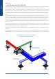
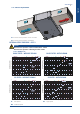
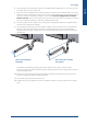
Table Of Contents
- CONTENTS
- 1. GENERAL RECOMMENDATIONS
- 2. INSPECTION AND STORAGE
- 3. WARRANTY
- 4. CONTENTS Of PACKAGE
- 5. DIMENSIONS
- 6. HANDLING
- 7. REFRIGERATION SPECIFICATIONS
- 8. TECHNICAL SPECIFICATIONS
- 9. ELECTRIC SPECIFICATIONS
- 10. INSTALLATION
- 11. DUCTING AND NOISE LEVEL REDUCTION
- 12. UNCLAMPING THE COMPRESSOR
- 13. HYDRAULIC LINKS
- 14. WIRING DIAGRAM AND LEGEND
- 15. ELECTRICAL CONNECTIONS
- 16. REGULATION
- 17. FINAL TASKS
- 18. STARTING - RECOMMENDATIONS - SETTINGS
- 19. MAINTENANCE AND SERVICING
- 19.1. FAULT FINDING
- 19.1.1. NEITHER THE FAN NOR THE COMPRESSOR OPERATE
- 19.1.2. VENTILATION (FAN) MODE OPERATES BUT THE COMPRESSOR DOES NOT OPERATE
- 19.1.3. INSUFFICIENT COOLING OR HEATING PRODUCTION
- 19.1.4. INSUFFICIENT WATER FLOW AT THE LEVEL OF THE COAXIAL EXCHANGER.
- 19.1.5. APPEARANCE OF WATER DROPLETS IN THE APPLIANCE
- 19.1.6. APPEARANCE OF ABNORMAL NOISES AND VIBRATIONS IN THE CASING
- 19.2. ALARM CODES
- 19.1. FAULT FINDING
- 20. IN CASE OF WARRANTY - MATERIAL RETURN PROCEDURE
- 21. ORDERING SERVICE AND SPARE PARTS ORDER
- DIMENSIONS
- CONFIGURATION R1.AI RECT/S4.AO RECT
- CONFIGURATION R2.AI RECT/S4.AO RECT
- CONFIGURATION R1.AI 1Ø200/S4.AO RECT OR R1.AI 1Ø200 FAØ100/S4.AO RECT OR R1.AI 1Ø200 FAØ125/S4.AO RECT
- CONFIGURATION R2.AI 1Ø200/S4.AO RECT OR R2.AI 1Ø200 FAØ100/S4.AO RECT OR R2.AI 1Ø200 FAØ125/S4.AO RECT
- CONFIGURATION R1.AI RECT/S4.AO 1Ø200 OR R1.AI RECT/S3.AO 1Ø200
- CONFIGURATION R2.AI RECT/S4.AO 1Ø200 OR R2.AI RECT/S3.AO 1Ø200
- CONFIGURATION R1.AI 1Ø200/S4.AO 1Ø200 OR R1.AI 1Ø200 FAØ100/S4.AO 1Ø200 OR R1.AI 1Ø200 FAØ125/S4.AO 1Ø200 OR R1.AI 1Ø200/S3.AO 1Ø200 OR R1.AI 1Ø200 FAØ100/S3.AO 1Ø200 OR R1.AI 1Ø200 FAØ125/S3.AO 1Ø200
- CONFIGURATION R2.AI 1Ø200/S4.AO 1Ø200 OR R2.AI 1Ø200 FAØ100/S4.AO 1Ø200 OR R2.AI 1Ø200 FAØ125/S4.AO 1Ø200 OR R2.AI 1Ø200/S3.AO 1Ø200 OR R2.AI 1Ø200 FAØ100/S3.AO 1Ø200 OR R2.AI 1Ø200 FAØ125/S3.AO 1Ø200
- CONFIGURATION AO XLN
- WIRING DIAGRAM
- DIMENSIONS
- CONFIGURATION R1.AI RECT/S4.AO RECT
- CONFIGURATION R2.AI RECT/S4.AO RECT
- CONFIGURATION R1.AI 1Ø200/S4.AO RECT OU R1.AI 1Ø200 FAØ100/S4.AO RECT OU R1.AI 1Ø200 FAØ125/S4.AO RECT
- CONFIGURATION R2.AI 1Ø200/S4.AO RECT OU R2.AI 1Ø200 FAØ100/S4.AO RECT OU R2.AI 1Ø200 FAØ125/S4.AO RECT
- CONFIGURATION R1.AI RECT/S4.AO 1Ø200 OU R1.AI RECT/S3.AO 1Ø200
- CONFIGURATION R2.AI RECT/S4.AO 1Ø200 OU R2.AI RECT/S3.AO 1Ø200
- CONFIGURATION R1.AI 1Ø200/S4.AO 1Ø200 OU R1.AI 1Ø200 FAØ100/S4.AO 1Ø200 OU R1.AI 1Ø200 FAØ125/S4.AO 1Ø200 OU R1.AI 1Ø200/S3.AO 1Ø200 OU R1.AI 1Ø200 FAØ100/S3.AO 1Ø200 OU R1.AI 1Ø200 FAØ125/S3.AO 1Ø200
- CONFIGURATION R2.AI 1Ø200/S4.AO 1Ø200 OU R2.AI 1Ø200 FAØ100/S4.AO 1Ø200 OU R2.AI 1Ø200 FAØ125/S4.AO 1Ø200 OU R2.AI 1Ø200/S3.AO 1Ø200 OU R2.AI 1Ø200 FAØ100/S3.AO 1Ø200 OU R2.AI 1Ø200 FAØ125/S3.AO 1Ø200
- CONFIGURATION AO XLN
- SCHEMAS ELECTRIQUES
- ABMESSUNGEN
- KONFIGURATION R1.AI RECT/S4.AO RECT
- KONFIGURATION R2.AI RECT/S4.AO RECT
- KONFIGURATION R1.AI 1Ø200/S4.AO RECT ODER R1.AI 1Ø200 FAØ100/S4.AO RECT ODER R1.AI 1Ø200 FAØ125/S4.AO RECT
- KONFIGURATION R2.AI 1Ø200/S4.AO RECT ODER R2.AI 1Ø200 FAØ100/S4.AO RECT ODER R2.AI 1Ø200 FAØ125/S4.AO RECT
- KONFIGURATION R1.AI RECT/S4.AO 1Ø200 ODER R1.AI RECT/S3.AO 1Ø200
- KONFIGURATION R2.AI RECT/S4.AO 1Ø200 ODER R2.AI RECT/S3.AO 1Ø200
- KONFIGURATION R1.AI 1Ø200/S4.AO 1Ø200 ODER R1.AI 1Ø200 FAØ100/S4.AO 1Ø200 ODER R1.AI 1Ø200 FAØ125/S4.AO 1Ø200 ODER R1.AI 1Ø200/S3.AO 1Ø200 ODER R1.AI 1Ø200 FAØ100/S3.AO 1Ø200 ODER R1.AI 1Ø200 FAØ125/S3.AO 1Ø200
- KONFIGURATION R2.AI 1Ø200/S4.AO 1Ø200 ODER R2.AI 1Ø200 FAØ100/S4.AO 1Ø200 ODER R2.AI 1Ø200 FAØ125/S4.AO 1Ø200 ODER R2.AI 1Ø200/S3.AO 1Ø200 ODER R2.AI 1Ø200 FAØ100/S3.AO 1Ø200 ODER R2.AI 1Ø200 FAØ125/S3.AO 1Ø200
- KONFIGURATION AO XLN
- STROMLAUFPLANS
- DIMENSIONI
- CONFIGURAZIONE R1.AI RECT/S4.AO RECT
- CONFIGURAZIONE R2.AI RECT/S4.AO RECT
- CONFIGURAZIONE R1.AI 1Ø200/S4.AO RECT O R1.AI 1Ø200 FAØ100/S4.AO RECT O R1.AI 1Ø200 FAØ125/S4.AO RECT
- CONFIGURAZIONE R2.AI 1Ø200/S4.AO RECT O R2.AI 1Ø200 FAØ100/S4.AO RECT O R2.AI 1Ø200 FAØ125/S4.AO RECT
- CONFIGURAZIONE R1.AI RECT/S4.AO 1Ø200 O R1.AI RECT/S3.AO 1Ø200
- CONFIGURAZIONE R2.AI RECT/S4.AO 1Ø200 O R2.AI RECT/S3.AO 1Ø200
- CONFIGURAZIONE R1.AI 1Ø200/S4.AO 1Ø200 O R1.AI 1Ø200 FAØ100/S4.AO 1Ø200 O R1.AI 1Ø200 FAØ125/S4.AO 1Ø200 O R1.AI 1Ø200/S3.AO 1Ø200 O R1.AI 1Ø200 FAØ100/S3.AO 1Ø200 O R1.AI 1Ø200 FAØ125/S3.AO 1Ø200
- CONFIGURAZIONE R2.AI 1Ø200/S4.AO 1Ø200 O R2.AI 1Ø200 FAØ100/S4.AO 1Ø200 O R2.AI 1Ø200 FAØ125/S4.AO 1Ø200 O R2.AI 1Ø200/S3.AO 1Ø200 O R2.AI 1Ø200 FAØ100/S3.AO 1Ø200 O R2.AI 1Ø200 FAØ125/S3.AO 1Ø200
- CONFIGURAZIONE AO XLN
- SCHEMA ELETRICO
- DIMENSIONES
- CONFIGURACIÓN R1.AI RECT/S4.AO RECT
- CONFIGURACIÓN R2.AI RECT/S4.AO RECT
- CONFIGURACIÓN R1.AI 1Ø200/S4.AO RECT O R1.AI 1Ø200 FAØ100/S4.AO RECT O R1.AI 1Ø200 FAØ125/S4.AO RECT
- CONFIGURACIÓN R2.AI 1Ø200/S4.AO RECT O R2.AI 1Ø200 FAØ100/S4.AO RECT O R2.AI 1Ø200 FAØ125/S4.AO RECT
- CONFIGURACIÓN R1.AI RECT/S4.AO 1Ø200 O R1.AI RECT/S3.AO 1Ø200
- CONFIGURACIÓN R2.AI RECT/S4.AO 1Ø200 O R2.AI RECT/S3.AO 1Ø200
- CONFIGURACIÓN R1.AI 1Ø200/S4.AO 1Ø200 O R1.AI 1Ø200 FAØ100/S4.AO 1Ø200 O R1.AI 1Ø200 FAØ125/S4.AO 1Ø200 O R1.AI 1Ø200/S3.AO 1Ø200 O R1.AI 1Ø200 FAØ100/S3.AO 1Ø200 O R1.AI 1Ø200 FAØ125/S3.AO 1Ø200
- CONFIGURACIÓN R2.AI 1Ø200/S4.AO 1Ø200 O R2.AI 1Ø200 FAØ100/S4.AO 1Ø200 O R2.AI 1Ø200 FAØ125/S4.AO 1Ø200 O R2.AI 1Ø200/S3.AO 1Ø200 O R2.AI 1Ø200 FAØ100/S3.AO 1Ø200 O R2.AI 1Ø200 FAØ125/S3.AO 1Ø200
- CONFIGURACIÓN AO XLN
- ESQUEMA ELECTRICO

English
Internal cladding on both sides
with glass fibre sound insulation
Adapter part
Alignment elbow
Main duct
Spur with internal glass fibre
sound insulation cladding
Air distributor:
60 x 60 cm (example)
Canvas connection
Heat pump
SUPPLY AIR
OUTDOOR AIR
RETURN AIR
10 SYSLOOP
Water circuit heat pumps are usually installed in conjunction with an air blowing duct. A return air duct may
also be required. All ductwork shall be compliant with best air conditioning engineering practices.
The air blowing duct system normally consists of a exible connector mounted on the unit, a bridging
section to link to the size of the main duct, a short section of straight duct, an elbow without a damper and
a main duct with spurs equipped with distribution grilles as illustrated in the drawing below. The sum total
of the bridging section angles must not be higher than 30°, otherwise there will be signicant performance
losses.
Do not connect the main duct directly to the unit without a bridging section to reduce the duct size to that of
the unit’s connection collar. In the event of using metal ducts, only the sides of the elbow section and all the
spur duct sections should be covered with breglass sound insulation for reducing the noise level. Fibreglass
duct panels are more sound absorbent and may enable the exible canvas connection to be eliminated.
The duct network must be laid out to avoid any rectilinear runs betweens the heat pump outlet and the air
distribution outlets.
The return air intake ducts can be connected to a grille/lter located at the base of a wall, then directed via
hollow partitions towards a ceiling mounted plenum or via ceiling mounted grilles. The ceiling grilles must
not be located directly below the air conditioning unit.
The return air intake duct can be connected directly to the standard lter bracket. (Lateral lter removal
advisable).
Do not drill panel screws directly into the unit’s casing for connecting the blowing and return air intake ducts,
especially on the air return side, as there is a risk of damaging the condensate recovery tray and the battery.
11. DUCTING AND NOISE LEVEL REDUCTION
Recommended layout diagram for installation
with several air distribution outlets